The link between an E_Port and EX_Port, or VE_Port and VEX_Port, is called an inter-fabric link (IFL). IFLs can be achieved using a FC router.
Why IFLs is needed?
IFL needs to be implemented when there is a need to have a communication with different Fabric without disturbing the current setup. IFL can be achieved with use of FC router.
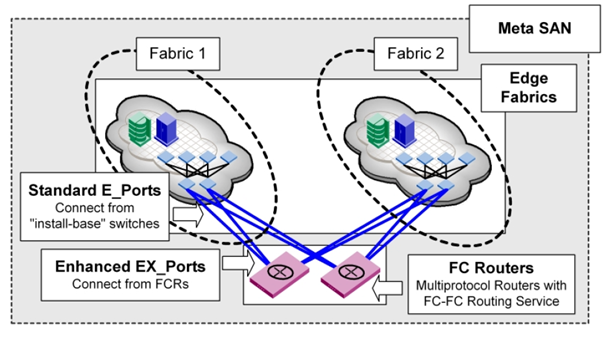
Meta SAN:
Meta-SAN is a collection of SAN devices, switches, edge fabrics, Logical Storage Area Networks (LSANs), and Routers that comprise a physically connected but logically partitioned storage network.
Meta SAN Example:
Terms to be known:
Backbone Fabric: A capability that enables scalable Meta SANs by allowing the networking of multiple routers that connects to the backbone fabric via E_Port interfaces. A backbone fabric is an intermediate network that connects two or more edge fabrics. A backbone fabric also enables hosts and targets in one edge fabric to communicate with devices in other edge or backbone fabrics.
Backbone-to-Edge Routing: Fibre Channel routers can connect to a common fabric–known as a backbone fabric E_Ports. A backbone fabric can be used as a transport fabric that interconnects edge fabrics. Fibre Channel routers also enable hosts and targets in edge fabrics to communicate with devices in the backbone fabric–this is known as backbone-to-edge routing.
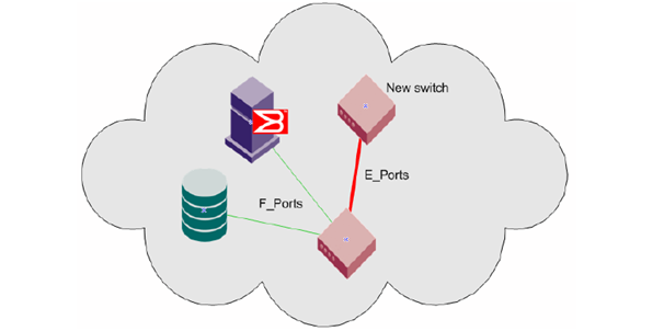
E_Port: A standard Fibre Channel mechanism that enables switches to network with each other.
Edge Fabric: A Fibre Channel fabric connected to a router via one or more EX_Ports. This is where hosts and storage are typically attached in a Meta-SAN.
Edge-to-Edge Routing: Occurs when devices in one edge fabric communicate with devices in another edge fabric through one or more Fiber Channel routers.
EX_Port: The type of E_Port used to connect a router to an edge fabric. An EX_Port follows standard E_Port protocols.
Exported Device: A device that has been mapped between fabrics. A host or storage port in one edge fabric can be exported to any other fabric through LSAN zoning.
Fabric ID (FID): Unique identifier of a fabric in a Meta-SAN. Every EX_Port and VEX_Port uses the FID property to identify the fabric at the opposite end of the IFL. You should configure all of the EX_Ports and VEX_Ports attached to the same edge fabric with the same FID. The FID for every edge fabric must be unique from each backbone fabric’s perspective.
Fibre Channel Network Address Translation (FC-NAT): A capability that allows devices in different fabrics to communicate when those fabrics have addressing conflicts. This is similar to the “hide-behind” NAT used in firewalls.
Fibre Channel Router Protocol (FCRP): A Brocade-authored standards-track protocol that enables LSAN switches to perform routing between different Edge fabrics, optionally across a backbone fabric.
FC-FC Routing Service: A service that extends hierarchical networking capabilities to Fibre Channel fabrics. It enables devices located on separate fabrics to communicate without merging the fabrics. It also enables the creation of LSANs.
Inter-Fabric Link (IFL): A connection between a router and an edge fabric. Architecturally, these can be of type EX_Port-to-E_Port or EX_Port-to-EX_Port.
Logical Storage Area Network (LSAN): A logical network that spans multiple fabrics. The path between devices in an LSAN can be local to an edge fabric or cross one or more Routers and up to one intermediate backbone fabric. LSANs are administered through LSAN zones in each edge fabric.
LSAN Zone: The mechanism by which LSANs are administered. A Router attached to two fabrics will “listen” for the creation of matching LSAN zones on both fabrics.
Meta-SAN: The collection of all devices, switches, edge and backbone fabrics, LSANs, and Routers that make up a physically connected but logically partitioned storage network
Phantom Domains: A phantom domain is a domain created by the Fibre Channel router. The FC router creates two types of phantom domains: front phantom domains and translate phantom domains.
Front phantom domain or front domain: a domain that is projected from the FC router to the edge fabric. There is one front phantom domain from each FC router to an edge fabric, regardless of the number of EX_Ports connected from that router to the edge fabric. Another FC router connected to the same edge fabric projects a different front phantom domain.
Translate phantom domain: Also known as xlate domain, is a router virtual domain that represents an entire fabric. The EX_Ports present xlate domains in edge fabrics as being topologically behind the front domains; if the xlate domain is in a backbone fabric, then it is topologically present behind the FC router because there is no front domain in a backbone fabric.
Proxy Devices: A proxy device is a virtual device presented into a fabric by a Fibre Channel router, and represents a real device on another fabric. When a proxy device is created in a fabric, the real Fibre Channel device is considered to be imported into this fabric. The presence of a proxy device is required for inter-fabric device communication. The proxy device appears to the fabric as a real Fibre Channel device, has a name server entry, and is assigned a valid port ID. The port ID is only relevant on the fabric in which the proxy device has been created.
Proxy ID:– The port ID of the proxy device.
VE_Port: Virtual E_Port; an FCIP tunnel without routing is a VE_Port.
VEx_Port: The type of VE_Port used to connect a router to an edge fabric. A VEx_Port follows standard E_Port protocols and supports FC-NAT but does not allow fabric merging across VEX_Ports.
How Inter Fabric Link Works?
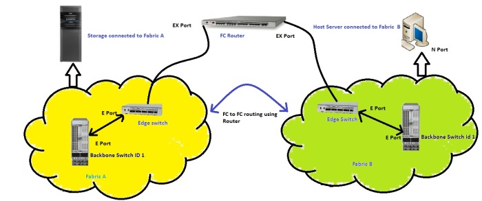
Let’s take a below example for Inter fabric Link and how it can be achieved.
In this example there are two separate fabrics in Fabric A storage node is connected and in Fabric B Host server is being connected. Now due to urgent requirement for additional storage there is a need for allocating 1 TB of storage to an Host in Fabric B, There is a problem now because Storage Node is present in Fabric A and Host server cannot contact storage as they are in different fabric. To solve this problem there is a introduction of FC routing concept and this is achieved using a FC router being connected to a Edge switch from both fabric. Now the Devices connected in a Fabric can communicate with Devices in Fabric B using Inter Fabric links and this concept is known as FC routing. Whole Fabric A and Fabric B connected through a FC router is called as LSAN.
How communications between 2 Fabrics occur?
Below are the steps involved in IFL communication.
Step 1: Disable the ports in Edge switch to be participated in IFLs
Step 2: Cable Edge switches of both fabric to FC router.
Step 3: Convert FC Router port as EX port, can be achieved using FC router Web Tools or Command Line.
Step 4: While configuring EX port set Fabric Id of the ports, Fabric Id should not be 1.
Step 5: Enable the ports. Now this will take some time communication between E and Ex ports.
Step 6: Now the If we want Host from Fabric B to access Fabric A we need to do LSAN Zoning.
Step 7: Create a Zone in Fabric B as LSAN_Zone Name and add Host WWPN and Storage WWPN in target side to get communicated. Enable the Zone configuration.
Step 8: Similarly Create a Zone in Fabric A as LSAN_Zone Name and Host WWPN and Storage WWPN in target side to get communicated. Enable the Zone configuration.
Step 9: When LSAN zoning has been done it takes some time to have a communication because FC Routing gets initialized when LSAN zoning gets completed.
Step 10: When communication gets established the Fabric A sees the Host as a Proxy Device present in Fabric A with Proxy Id, Similarly Fabric B sees the Storage Node as a Proxy Device with Proxy Id. Now the storage can be allocated to Fabric B host server.


