FAST VP Implementation

Fully Automated Storage Tiering:

FAST allows administrator to define policies and automate the movement of Luns between the Tiers based on the priority.

Advantage of FAST:

  1. Based on the load the Luns can be placed to High performance Storage tiers EFD.
  2. Low Used storages are moved to SATA disk group.

Storage Tiers: Collection of same type of storage.

There are 3 Kind of storage tiers available in VMAX:

  1. EFD
  2. FC
  3. SATA

VNX contains 3 types of storage Tiers:

  1. EFD
  2. SAS
  3. NL SAS

We won’t focus on FAST implementation for Thick devices because now a days provisioning of Thick devices are not advised.

FAST VP:

FAST VP is used for the implementation of FAST in Virtual provisioning.

fast TierLet’s see How FAST VP works:

  1. There will be Thin devices being created and allocated to a certain FAST policy.
  2. Based on the FAST policy defined the highly utilized data from Sub Lun levels are identified.
  3. Sub Lun highly utilized are moved to Storage Tier Flash.
  4. Sub Lun underutilized are moved to SATA storage Tier.
  5. The FAST VP will identify highly utilized Sub Luns based on the Symmetrix Microcode and FAST controller.

Components of FAST VP:

Comp

Components description:

EMC Symmetrix has two components one is Microcode which resided in Symmetrix Operating system and other is FAST controller residing in Service process.

  1. Performance Data Collection:

Constant performance and CPU utilization of Thin Luns are determined in Sub Lun Levels.

  1. Performance Data Analysis:

Performance data collected are analyzed in the FAST controller.

  1. Intelligent Tiering Algorithm:

Data collected through Micro code and Analysis report generated by FAST controller are used by Intelligent Tiering Algorithm to issue a Sub Lun movement to VLUN VP data Movement Engine.

  1. Allocation Compliance algorithm:

Enforces upper limit of Storage Tier can be used for Sub Lun Data Movement for each Storage groups.

  1. VLUN VP Data Movement Engine:

Based on the Intelligent Tiering algorithm the Extent of data are moved between Tiers.

FAST VP has two modes of operation:

  1. Automatic: Data Movement and Data Analysis are continuously performed.
  2. Off Mode: Only performance statistics will be collected, No data movements will take place.

Elements of FAST VP:

tier

Storage Tier:

Collection of drive technology like EFD, FC, SATA.

Storage Group:

Collection of host accessible devices.

FAST Policy:

Percentage of storage capacity between the storage tiers can be used by storage group.

Control Parameters for FAST VP:

  1. Movement Mode: Automatic or Off
  2. Relocation rate: Amount of data that can be moved at a Time. They are measured from 1 to 10, Default value is 5; 1 is the highest value and 10 is the lowest value.
  3. Reserved capacity Limit: Percentage of Virtual pool reserved for Non FAST activity. If we reach this level then FAST movement will not be performed.
  4. Workload analysis time: Amount of work load analysis samples to be collected.
  5. Initial period: Minimum amount of work load analysis needs to be completed before analyzing the sample.

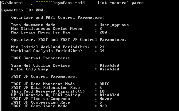
Sample FAST VP control Parameters:

control

Time Windows for FAST VP:

  1. Performance Time Window:

Collecting performance data 24×7. This time window can be changed but not recommended by EMC.

  1. Move Time window:

Time window during which sub Luns can be moved.

FAST implementation steps:

  1. Enable FAST VP.
  2. Set Control Parameters.
  3. Create Storage Tier.
  4. Create FAST Policy.
  5. Associate storage group to FAST Policy.
  6. Enable Time Windows setting.

Pre Checks:

Check for FAST VP licenses:

License can be checked using below command:

Symlmf list –type emclm –sid XXX

Always check with EMC before implementing FAST VP and get the suggestion for control parameters setting and time windows setting.

  1. Enable FAST VP:

Command to enable FAST VP.

Symfast –sid XX enable –vp

To List the states of FAST VP:

Symfast –sid XX list –state

  1. Set Control Parameters settings:

To List control parameters:

Symfast –sid xxx list –control_parms

To change control parameters setting:

symfast -sid XXX set -control_parms -mode AUTO_APPROVE -max_simult_devs 8 -max_devs 240 -min_perf_period 2 -workload_period 24 -vp_data_move_mode AUTO -vp_reloc_rate 5 -pool_resv_cap 20 -vp_allocation_by_fp disable

  1. Create Storage Tier:

Symtier is the command used for creating Storage tier.

RAID protection for Tier creation:

RAID 0 = -tgt_unprotected 
RAID 1 = -tgt_raid1 
RAID 5 = -tgt_raid5 -tgt_prot 3+1, -tgt_raid5 -tgt_prot 7+1
RAID 6 = -tgt_raid6 -tgt_prot 6+2 , -tgt_raid6 -tgt_prot 14+2

We had already created three pools named EFD,FC,SATA.

Creating EFD Tier:

symtier -sid xxx create -name EFD_VP_Tier -tgt_raid5 -tgt_prot 7+1 -technology EFD -vp -pool PoolName –EFD

 Creating FC Tier:

 symtier -sid xxx create -name FC_VP_Tier -tgt_raid5 -tgt_prot 3+1 -technology FC  -vp -pool PoolName –FC

 Creating SATA Tier:

 symtier -sid xxx create -name FC_SATA_Tier -tgt_rai6 -tgt_prot 6+2 -technology SATA  -vp -pool PoolName –SATA

 To List Tiers:

Symfast –sid XXX list

1

4. Create FAST Policy:

Create FAST VP policy.

symfast -sid xxx -fp create -name EFD_VP

Add Storage Tiers to FAST Policy.

symfast -sid xxx -fp add -tier_name EFD_VP_Tier  -max_sg_percent 100 -fp_name EFD_VP

symfast -sid xxx -fp add -tier_name FC_VP_Tier -max_sg_percent 20 -fp_name EFD_VP

symfast -sid xxx -fp add -tier_name SATA_VP_Tier -max_sg_percent 10 -fp_name EFD_VP

Maximum 300% for Storage tier can be allocated to a FAST Policy.

To list FAST VP policy:

Symfast list –sid 606 –fp -vp


2

5. Associate storage group to FAST Policy:

Storage groups will be created while Auto provisioning for a host.

Associate a Storage group to a FAST policy.

symfast -sid xxx associate -sg Storage_group -fp_name EFD_VP -priority 2 

Storage group associated with fast policy will be assigned a priority between 1 to3. 1 is highest, 3 is lowest and 2 is default priority. 

To List association: 

symfast -sid xxx list –association 

6. Enable Time Windows setting: 

To List Time window:

Symtw list –sid XXX

To Change the Move Time Window setting: 

symtw -sid XXX add -type MOVE_VP -days mon,tue,wed,thu,fri,sat,sun -start_time 18:00 -end_time 24:00 –inclusive

 To Change performance Time Window:

symtw -sid xxx -inclusive -type perf add -days Mon,Tue,Wed,Thu,Fri,Sat,Sun -start_time 00:00 -end_time 24:00

Mostly Performance time windows are not changed. Default time windows are preferred for performance time window setting.

Inter Fabric Links

The link between an E_Port and EX_Port, or VE_Port and VEX_Port, is called an inter-fabric link (IFL). IFLs can be achieved using a FC router.

Why IFLs is needed?

IFL needs to be implemented when there is a need to have a communication with different Fabric without disturbing the current setup. IFL can be achieved with use of FC router.

Meta SAN:

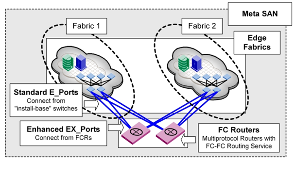
Meta-SAN is a collection of SAN devices, switches, edge fabrics, Logical Storage Area Networks (LSANs), and Routers that comprise a physically connected but logically partitioned storage network.

Meta SAN Example:

LSAN

Terms to be known:

Backbone Fabric: A capability that enables scalable Meta SANs by allowing the networking of multiple routers that connects to the backbone fabric via E_Port interfaces. A backbone fabric is an intermediate network that connects two or more edge fabrics. A backbone fabric also enables hosts and targets in one edge fabric to communicate with devices in other edge or backbone fabrics.

Backbone-to-Edge Routing: Fibre Channel routers can connect to a common fabric–known as a backbone fabric E_Ports. A backbone fabric can be used as a transport fabric that interconnects edge fabrics. Fibre Channel routers also enable hosts and targets in edge fabrics to communicate with devices in the backbone fabric–this is known as backbone-to-edge routing.
E_Port: A standard Fibre Channel mechanism that enables switches to network with each other.

Edge Fabric: A Fibre Channel fabric connected to a router via one or more EX_Ports. This is where hosts and storage are typically attached in a Meta-SAN.

Edge-to-Edge Routing: Occurs when devices in one edge fabric communicate with devices in another edge fabric through one or more Fiber Channel routers.

EX_Port: The type of E_Port used to connect a router to an edge fabric. An EX_Port follows standard E_Port protocols.

Exported Device: A device that has been mapped between fabrics. A host or storage port in one edge fabric can be exported to any other fabric through LSAN zoning.
Fabric ID (FID): Unique identifier of a fabric in a Meta-SAN. Every EX_Port and VEX_Port uses the FID property to identify the fabric at the opposite end of the IFL. You should configure all of the EX_Ports and VEX_Ports attached to the same edge fabric with the same FID. The FID for every edge fabric must be unique from each backbone fabric’s perspective.

Fibre Channel Network Address Translation (FC-NAT): A capability that allows devices in different fabrics to communicate when those fabrics have addressing conflicts. This is similar to the “hide-behind” NAT used in firewalls.

Fibre Channel Router Protocol (FCRP): A Brocade-authored standards-track protocol that enables LSAN switches to perform routing between different Edge fabrics, optionally across a backbone fabric.

FC-FC Routing Service: A service that extends hierarchical networking capabilities to Fibre Channel fabrics. It enables devices located on separate fabrics to communicate without merging the fabrics. It also enables the creation of LSANs.

Inter-Fabric Link (IFL): A connection between a router and an edge fabric. Architecturally, these can be of type EX_Port-to-E_Port or EX_Port-to-EX_Port.

Logical Storage Area Network (LSAN): A logical network that spans multiple fabrics. The path between devices in an LSAN can be local to an edge fabric or cross one or more Routers and up to one intermediate backbone fabric. LSANs are administered through LSAN zones in each edge fabric.

LSAN Zone: The mechanism by which LSANs are administered. A Router attached to two fabrics will “listen” for the creation of matching LSAN zones on both fabrics.

Meta-SAN: The collection of all devices, switches, edge and backbone fabrics, LSANs, and Routers that make up a physically connected but logically partitioned storage network

Phantom Domains: A phantom domain is a domain created by the Fibre Channel router. The FC router creates two types of phantom domains: front phantom domains and translate phantom domains.

Front phantom domain or front domain: a domain that is projected from the FC router to the edge fabric. There is one front phantom domain from each FC router to an edge fabric, regardless of the number of EX_Ports connected from that router to the edge fabric. Another FC router connected to the same edge fabric projects a different front phantom domain.

Translate phantom domain: Also known as  xlate domain, is a router virtual domain that represents an entire fabric. The EX_Ports present xlate domains in edge fabrics as being topologically behind the front domains; if the xlate domain is in a backbone fabric, then it is topologically present behind the FC router because there is no front domain in a backbone fabric.

Proxy Devices: A proxy device is a virtual device presented into a fabric by a Fibre Channel router, and represents a real device on another fabric. When a proxy device is created in a fabric, the real Fibre Channel device is considered to be imported into this fabric. The presence of a proxy device is required for inter-fabric device communication. The proxy device appears to the fabric as a real Fibre Channel device, has a name server entry, and is assigned a valid port ID. The port ID is only relevant on the fabric in which the proxy device has been created.

Proxy ID:– The port ID of the proxy device.

VE_Port: Virtual E_Port; an FCIP tunnel without routing is a VE_Port.

VEx_Port: The type of VE_Port used to connect a router to an edge fabric. A VEx_Port follows standard E_Port protocols and supports FC-NAT but does not allow fabric merging across VEX_Ports.

How Inter Fabric Link Works?

Let’s take a below example for Inter fabric Link and how it can be achieved.

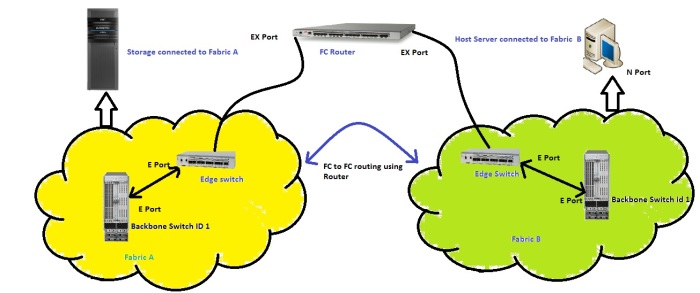
FC Routing

In this example there are two separate fabrics in Fabric A storage node is connected and in Fabric B Host server is being connected. Now due to urgent requirement for additional storage there is a need for allocating 1 TB of storage to an Host in Fabric B, There is a problem now because Storage Node is present in Fabric A and Host server cannot contact storage as they are in different fabric. To solve this problem there is a introduction of FC routing concept and this is achieved using a FC router being connected to a Edge switch from both fabric. Now the Devices connected in a Fabric can communicate with Devices in Fabric B using Inter Fabric links and this concept is known as FC routing. Whole Fabric A and Fabric B connected through a FC router is called as LSAN.
How communications between 2 Fabrics occur?

Below are the steps involved in IFL communication.

Step 1: Disable the ports in Edge switch to be participated in IFLs

Step 2: Cable Edge switches of both fabric to FC router.

Step 3: Convert FC Router port as EX port, can be achieved using FC router Web Tools or Command Line.

Step 4: While configuring EX port set Fabric Id of the ports, Fabric Id should not be 1.

Step 5: Enable the ports. Now this will take some time communication between E and Ex ports.

Step 6: Now the If we want Host from Fabric B to access Fabric A we need to do LSAN Zoning.

Step 7: Create a Zone in Fabric B as LSAN_Zone Name and add Host WWPN and Storage WWPN in target side to get communicated. Enable the Zone configuration.
Step 8: Similarly Create a Zone in Fabric A as LSAN_Zone Name and Host WWPN and Storage WWPN in target side to get communicated. Enable the Zone configuration.

Step 9: When LSAN zoning has been done it takes some time to have a communication because FC Routing gets initialized when LSAN zoning gets completed.

Step 10: When communication gets established the Fabric A sees the Host as a Proxy Device present in Fabric A with Proxy Id, Similarly Fabric B sees the Storage Node as a Proxy Device with Proxy Id. Now the storage can be allocated to Fabric B host server.

Inter Switch Link

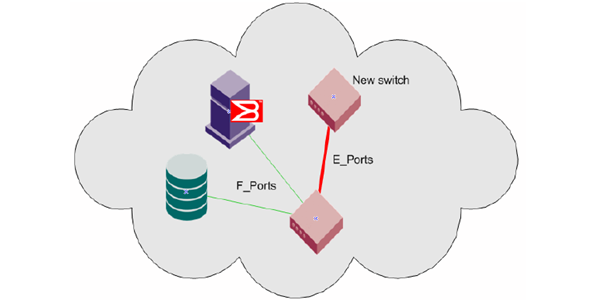
A Link between two switches are known as Inter Switch Link. The Link between two switches are known as E-Port to E-Port Link. The ports of the two switches automatically come online as E_Ports once the login process finishes successfully between two switches when connected. While connecting two switches a point to be noted is that both switches should not have same Domain Id.

4

The factors to be considered while performing Inter switch link.

Below mentioned Parameters needed to be different while performing ISL.

  • Domain ID
  • Switch name
  • Chassis name

When configuring a Brocade switch for ISL  always maintain a certain ports from switch for ISL links. When ISL configured there are certain problems like congestion, This problem can be solved by using ISL Trunking.

Inter Switch Link Trunking:

Aggregation of four ISLs into a single logical 8 Gb/s trunk group, this feature supports efficient high-speed communications throughout Storage Area Networks (SANs).

ISL Trunking can dramatically improve the performance, manageability, and reliability.

Let’s take an example for ISL congestion problems.

5

When two switches gets connected there is a ISL link and the network traffic starts to flow through this link to other switch. If due to some failure the Link gets disrupted there is congestion and there is a loss of frames. Another problem is ISL will not utilize full The ISL Trunking feature allows up to four Inter switch Links (ISLs) to merge logically into a single link. An ISL is a connection between two switches through an Expansion Port (E_Port). When using ISL Trunking to aggregate bandwidth of up to four ports, the speed of the ISLs between switches in a fabric is quadrupled. Bandwidth; to solve this problem the ISL Trunking concept has been developed.

ISL Trunking:

6

The ISL Trunking feature allows up to four Inter switch Links (ISLs) to merge logically into a single link. When using ISL Trunking to aggregate bandwidth of up to four ports, the speed of the ISLs between switches in a fabric is quadrupled.

In ISL Trunking the congestion problem can be solved using Dynamic Path selection methodology and the total Bandwidth gets aggregated to give maximum bandwidth.

Inter Chassis Link

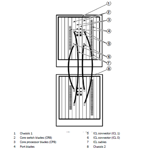
Inter Chassis Link is a Brocade DCX feature to connect two DCX Chassis together. ICL provides a dedicated blade for switch ports for end devices in the fabric by transporting traffic between chassis over dedicated high-speed links.

1

In an ICL blade there is 64×8 Gbps links available in DCX chassis Link. And in DCX-4S there is 32×8 Gbps link available. In an Backbone DCX switch the slot 5 and 8 are the ICL blades and these blades are connected through the supported topologies. Ports through which 2 ICl blades get connected are called as E_port(Expansion port).

ICL link features for DCX and DCX-4S:

  • Speed locked at 8 Gbps.
  • Copper-based proprietary cable and connector.
  • No SFPs.
  • Each cable provides up to 16 x 8 (128) Gbps bandwidth on the DCX and up to 8 x 8 (64) Gbps bandwidth on the DCX-4S.
  • Licensed feature.
  • ICL cables are 2 meters in length.
  • Allows for ISL connections without consuming user ports.

There are two supported topologies for for ICL connections.

  1. Dual chassis configuration.
  2. Triangular configuration.

Now Let’s discuss about both configuration.

Dual chassis configuration:

2

In a Dual chassis configuration two DCX switches gets connected through core switch blades.

Triangular configuration:

3

In Triangular configuration two ICLs connect two Brocade DCX Backbones and one Brocade DCX-4S.

Supported Triangular configuration:

  1. 2 x DCX, and 1 x DCX-4S
  2. 1 x DCX and 2 x DCX-4S
  3. 3 x DCX-4S

Virtual Fabrics

Virtual Fabrics is a procedure to partition a Switch in to Logical switches. Each switch has its own data, control, and management paths.

Virtual Fabrics are called VSAN in CISCO so don’t get confused when someone asks about Virtual Fabrics.

a

Logical Switches:

Logical switches are the fundamental for Logical Fabrics. When Virtual fabrics are enabled a switch can be divided in to multiple logical switches. Ports and resources of switch can be shared dynamically to the logical switches.

Logical Switch features:

  • A Logical Switch can be configured in any mode, including McDATA Fabric or McDATA Open Fabric mode.
  • Allocate fabric resources per port rather than per switch
  • Simplify chargeback for storage by customer, department, application, or storage tier
  • Consolidate resources across multiple fabrics
  • Logical fabrics can be deployed Non Disruptively in existing SAN environment.
  • Improved ISL bandwidth utilization.

Logical switches are divided in to three.

  1. Default Logical Switch.
  2. Logical Switch.
  3. Base Switch.

  1. Default Logical Switch:

             Default Logical switches are created when Virtual fabrics are enabled.

            Default Logical switches contains all the physical ports and resource.

            In a Switches a ports to other logical switches can be assigned through chassis administrator.

     2. Logical Switch:

            User creates logical switches.

            Ports and resource to the logical switches are assigned from Default logical switches through Chassis administrator.

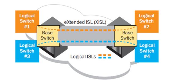
     3. Base Switch:

bb

            Base switch is a user defined switch.

            In a Physical switch only one Base switch can be present.

            Base switch provides a methodology for other logical switches to communicate with each other.

            Connection between two Base switches is called Extended Inter switch links.

            Logical switches are having Fabric ID assigned to every logical switches.

            This FCID helps switches to communicate with each other through XISL.

            When Logical switches with the same FID are configured to use the Base Switches automatically create a Logical ISL within the XISL.

            LISL isolates traffic from multiple fabrics.

            LISL is dedicated to traffic for a single fabric.

Device Login Process

Device Login process is a process when a new devices gets connected to a Fabric it gets registered with fabric so that it can communicate with other devices in the Fabric.

A device communicating in the fabric can be a Host server with Solaris, windows, Linux or a storage device. All kind of devices need to be registered with Switch for communicating with other devices.

Device Login process categorized in to 2 process a. FLOGI b. PLOGI

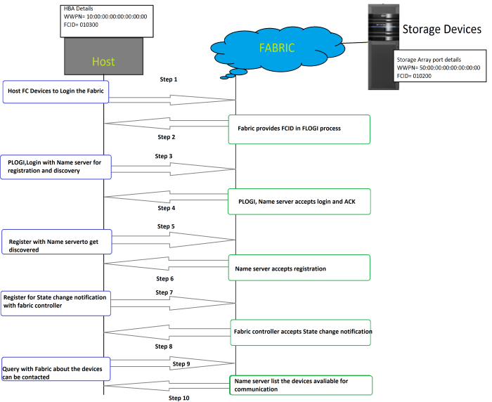
Below mentioned is the process explaining the Device Login process:

Device Login

I have tried to categorize Device login in to steps. Now let’s look in to it.

FLOGI:

FLOGI is a process where a Device gets it Fabric address which is a 24 Bit address.

Step 1 (FLOGI)

FLOGI (Fabric Login) the first frame transmitted by an Node device that is attempting to attach to a switch.  The FLOGI contains many bits of information about this initializing end device (N_Port).

Step 2 (FLOGI ACC)

Switch will respond to the FLOGI with an FLOGI ACC.  The format of the FLOGI ACC is identical to the FLOGI request but the information contained within it will be specific to the responding switch/switch port and Fabric Identifier gets assigned to Node.

Step 3 (PLOGI Name Server):

Node port sends a PLOGI signal to Name server so that node is able to register with and send queries to the Name Server.

Step 4 (PLOGI ACC):

Switch will respond the node port request for port Login with Acknowledgement.

Step 5 (Register with the Name Server):

Once PLOGI gets acknowledged then Node port can register with Name server for discovery of Target storage devices or SAN Devices.

Step 6 (Name Server Accepts registrations):

Name server accepts the Node ports registration with Name server.

Step 7 (SCR – State Change Registration):

Node Port will request the switch Fabric controller to send it a Registered State Change Notification (RSCN) every time something in the fabric changes.

Step 8 (State Change Registration ACK):

Fabric controller will accepts the SCR notification request with the switch.

Step 9(Query Name server):

Query Name server for the list of devices Node port can contact with in a fabric.

Step 10(Name server response):

Name server will respond to the Node port request and it will send the list of devices it can contact.

In this Device login process we could see that Fabric services like Fabric Login, Name server and Fabric controller participate in device Login process.

Some services are used in Zoning, In my next post I will explain Zoning and Switch services used in Zoning.

Brocade Fabric OS

Brocade fabric OS helps us to configure, manage and maintain a SAN as per needs of user.11

Fabric OS Core Functions

  1. Automatic discovery of devices: Fabric devices log in to the Simple Name Server SNS). Translative mode is automatically set to allow fabric initiators to communicate with private loop targets.
  2. Universal port support: Fabric OS identifies port types and automatically initializes each connection specific to the attached Fibre Channel system, whether it is another switch, host, private loop, or fabric-aware target system.
  3. Continuous monitoring of ports for exception conditions: Fabric OS disables data transfer to ports when they fail.

Brocade supports various Fabric services for reconfiguration of Brocade switches as per fabric needs. Now Let’s Discuss about Brocade fabric services.

2

In My next post I will be explaining how this fabric services are being used using Device login process

Fabric Login Services:

  • The Fabric Login server assigns a fabric address to a fabric node, which allows it to

Communicate with services on the switch or other nodes in the fabric.

  • The fabric address is a 24-bit address (0x000000) containing three 3-byte nodes.

Directory Services:

  • The directory server or name server registers fabric and public nodes and conducts queries to discover other devices in the fabric.

Fabric Controller: 

  • Fabric controller provides State Change Notifications (SCNs) to registered nodes when a change in the fabric topology occurs.

 Time Server: 

  • Time server sends the time to the member switches in the fabric from the principal switch.

 Management server: 

  • Single point for managing the Fabric or switch.
  • Allows a SAN management application to retrieve information and administer interconnected switches, servers, and storage devices.
  • The management server assists in the auto discovery of switch-based fabrics and their associated topologies.

Alias server: 

  • Helps to assign single name for group of nodes or WWPN.

Broadcast server: 

  • When frames are transmitted to address FFFFFF, then frames are replicated to all the nodes N and NL ports. I have never seen this address being used it is a optional fabric services.

 Brocade provides Dynamic Routing Services for high availability and maximum Performance:

1. Dynamic path selection via link-state protocols: Uses Fabric Shortest Path First (FSPF) to select the most efficient route for transferring data in a multi switch environment.

  1. Load sharing to maximize throughput through Inter-Switch Links (ISLs): Supports high throughput by using multiple ISLs between switches.
  2. Automatic path failover: Automatically reconfigures alternate paths when a link fails. Fabric OS distributes the new configuration fabric wide and reroutes traffic without manual intervention.
  3. In-order frame delivery: Guarantees that frames arrive in order.
  4. Automatic rerouting of frames: When a fault occurs reroutes traffic to alternative paths in the fabric without interruption of service or loss of data.
  5. Support for high-priority protocol: Ensures that frames identified as priority frames receive priority routing to minimize latency.
  6. Static routing support: Allows network managers to configure fixed routes for some data traffic and ensure resiliency during a link failure.
  7. Automatic reconfiguration: Automatically reroutes data traffic onto new ISLs when they are added to the SAN fabric.

Management of Brocade switches using End to End Management:

  1. Management Server based on FC-GS-3.
  2. SNMP Agent.
  3. In Band using External IP Interface.
  4. Syslog Daemon interface.
  5. Switch Beaconing.

Brocade optional Services: 

  1. Zoning: 

Zoning is a fabric-based service that enables you to partition your storage area network (SAN) into logical groups of devices that can access each other. 

  1. Encryption services:

The in-flight encryption and compression features allow frames to be encrypted or compressed at the point of an ISL between two Brocade switches, and then to be decrypted or decompressed at the ingress point of the ISL.

  1. Web Tools:

A web tool provides a GUI interface to manage the brocade switches.

  1. Quick Loops:

Brocade OS excludes intelligent hubs by creating virtual loops and this virtual loops provides the function of Hub.

  1. Extended Fabrics:

 Extended Fabrics re configures the switch to support the rigors of transmitting I/O  over long distances in conjunction with technologies such as Dense Wave Division Multiplexing (DWDM)

Fibre Channel Components

Fibre Cables:

Fibre signals can be driven through Optical signal or Electrical signal.

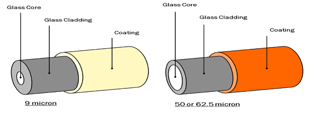
The fibre cables will have a Glass core through which the Optical signals pass. And then a Glass cladding are wrapped over the Fibre cables. The cladding is then supported with a coating.

There are two types of cables available one with 9 Micron for Single mode of communication and cables with 50 to 62.5 Micron for Multi-mode communication.

1

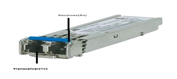
Optical fibre link consists of 2 links Transceiver and receiver

2

Single Mode & Multi Mode fibre:

3

Single Mode fibre is used for longer distances. Light travels in straight line and major application for single mode fibre are for long distances up to 10 KM.

Multi-Mode fibre is used for shorter communication. MMF allows multiple light to pass through and MMF uses Modal dispersion to achieve Multi Mode.

Fibre cables:

1

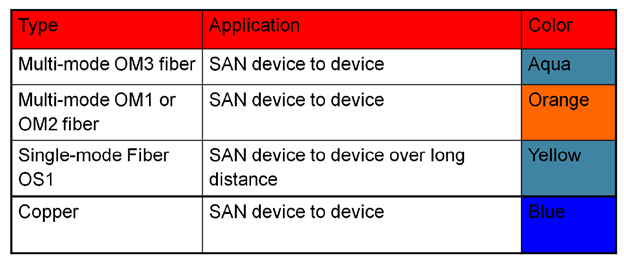
Cable color coding and application:

4

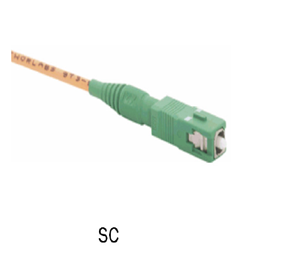
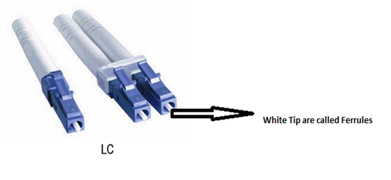
Fibre Optical Cable connector:

  1. SC connector: Used for switch with 1 Gbps.1

     2. LC connector: Used for Fibre with 2Gbps and above speed.2

    3. Small Form Factor(SFP)3

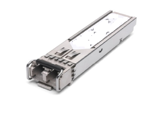
    These types are used for high speed cables. Provide high speed and hot swappable from 1 Gbps to 10 Gpbs. For high speed up to 10 Gbps we can use 10 Gigabit small form factor pluggable (XFP).


    Host Bus Adapter (HBA):

    HBA connects a host system to other network and storage devices.

    Various vendors are available when comes to HBA.3Vendors:

    1. Qlogic
    2. Emulex LightPulse
    3. Brocade
    4. Cisco

Fibre Channel Basics

Fibre channel protocol:

An ANSI standard for providing flexible serial data transport at long distances. Fiber channel is a high-speed network technology (commonly running at 2-, 4-, 8- and 16 GB/s rates) primarily used to connect storage subsystem

Various variant of Fiber Channels available. Below table is the List of fibre channel variant available in market.

NAME

Throughput

1GFC

200

2GFC

400

4GFC

800

8GFC

1,600

10GFC

2,400

16GFC

3,200

32GFC (Still under development)

6,400

 Fibre Channel Benefits:

  • Lossless Transmission.
  • Advanced flow control system to guarantee.
  • Multipurpose network infrastructure for connecting open systems.
  • Various system support (AIX,Windows,Linux,HP-UX)
  • Support Full duplex speed up to 1,2,4,8,16 Gbps.

Fibre Channel Topologies:

There are 3 type for Fiber channel topologies:

  1. Point to Point.
  2. Arbitrated Loop.
  3. Switched Fabric.

Now let’s discuss about them.

1. Point-to-point (FC-P2P):

 Two devices are connected directly to each other.

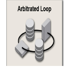
P2P2. Arbitrated loop (FC-AL):

 All devices are in a loop or ring, similar to token ring networking.

AL

  • Adding or removing a device from the loop causes all activity on the loop to be interrupted.
  • The failure of one device causes a break in the ring.
  • Fibre Channel hubs exist to connect multiple devices together and may bypass failed ports.
  • A loop may also be made by cabling each port to the next in a ring.


 2. switched fabric (FC-SW):

 All devices or loops of devices are connected to fibre channel switches.

  • Large number of servers and storage subsystems are connected using fibre channel switches.
  • Switches can be cascaded to form a fabric.

 SF

Features of Switched fabrics:

  • FC Network topology.
  • Maximum possible nodes.
  • Higher overall throughput.
  • Scaling is easy and various topology can be connected to form a FABRIC.

Fabric:

  • Connection of fibre channel switches or devices capable for routing frames using Destination ID.

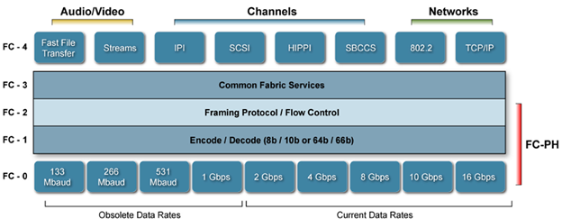
Fibre Channel Layers:

Layer

  • FC0– Physical, includes cabling, connectors like SFP.
  • FC1– Data link layer, which implements Line coding of signals.
  • FC2– Network layer, defined by the FC-PI-2 standard, consists of the core of fibre channel, port to port connections, Process to deliver a frame.
  • FC3– Common services layer, a thin layer that could eventually implement functions like encryption redundancy algorithms, multiport connections.
  • FC4– Protocol-mapping layer, Implements how protocol like SCSI are mapped to information unit.

Various types of ports in Switched fabric:

  • N_portis a port on the node (e.g. host or storage device) used with both FC-P2P or FC-SW topologies. Also known as node port.
  • NL_portis a port on the node used with an FC-AL topology. Also known as Node Loop port.
  • F_portis a port on the switch that connects to a node point-to-point (i.e. connects to an N_port). Also known as fabric port. An F_port is not loop capable.
  • FL_portis a port on the switch that connects to a FC-AL loop (i.e. to NL_ports). Also known as fabric loop port.
  • E_portis the connection between two fibre channel switches. Also known as an Expansion port. When E_ports between two switches form a link, that link is referred to as an inter-switch link (ISL).
  • B_portA Bridge Port is a Fabric inter-element port used to connect Bridge devices with E_Ports on a Switch. The B_Port provides a subset of the E_port functionality
  • D_portis a diagnostic port, used solely for the purpose of running link-level diagnostics between two switches and to isolate link level fault on the port, in the SFP, or in the cable.
  • EX_portis the connection between a fibre channel router and a fibre channel switch. On the side of the switch it looks like a normal E_port, but on the side of the router it is an EX_port.
  • TE_port *Is an extended ISL or EISL. The TE_port provides not only standard E_port functions but allows for routing of multiple VSANs


Data Domain Overview

DDEMC Data Domain Systems:

EMC Data Domain storage systems are traditionally used for disk backup, archiving, and disaster recovery.

EMC Data Domain system can also be used for online storage with additional features and benefits.

A Data Domain system can connect to your network via Ethernet or Fibre Channel connections.

Data Domain systems use low-cost Serial Advanced Technology Attachment (SATA) disk drives and implement a redundant array of independent disks (RAID) 6 in the software. RAID 6 is block-level striping with double distributed parity.

Note: Data Domain uses only RAID 6 no other raids are possible.

 Most Data Domain systems have a controller and multiple storage units.

  Hardware Overview:

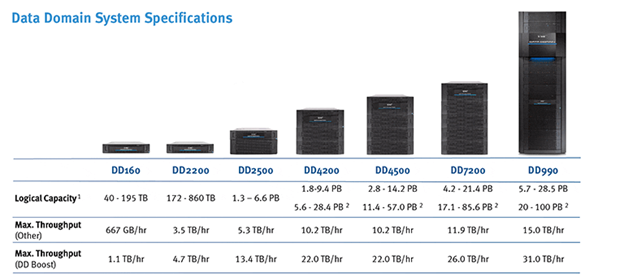
Data Domain Models available:

sep

Data Domain hardware consists of Controller and Disk Array Enclosure.

I will be explaining Data Domain 990 model hardware overview in this blog.

Hardware overview:

Two components: a. Controller b. Disk Shelf

Data Domain components in chassis:

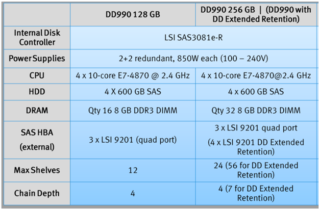
  1. Quad-socket, 10-core Xeon processors (Westmere-EX)
  2. Two memory configurations available
  3. Base: 128 GB supports up to 360 TB raw, 285 TB usable
  4. Expanded: 256 GB supports up to 720 TB raw, 570 TB usable
  5. External expansion using ES30 and ES20 shelves
  6. Three quad-port 6 Gb/s SAS HBAs for external connectivity
  7. Connectivity up to 24 shelves, or up to max capacity
  8. Four I/O slots for data access connectivity
  9. Up to four dual-port 1 GbE NICs, optical
  10. Up to four quad-port 1 GbE NICs, copper
  11. Up to three dual-port 10 GbE NICs, copper with SFP+ interface
  12. Up to three dual-port 10 GbE NICs, optical with LC interface
  13. Up to three dual-port 8 Gb Fibre Channel VTL HBAs
  14. Two 2 GB remote-battery NVRAM with Battery Backup Unit

 Two types of configuration are available in DD990. One DD990 with 128 GB RAM and second one is DD990 with 256 GB.

Sepc

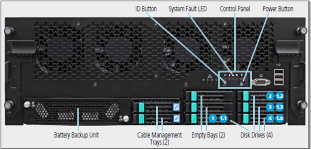
DD990 chassis enclosure View:

Controller Module Front and Back panel View.

Controller Front panel View

c1

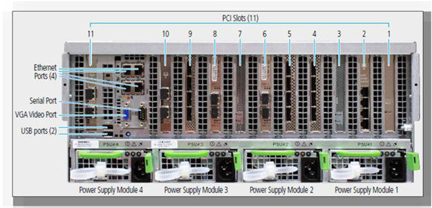
Controller Back Panel View

c2

Disk Shelf Front View:

d1

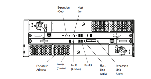
Disk Shelf Back View:

d2

Software overview:

Overview:

 Support for leading backup, file archiving, and email archiving applications

  • Simultaneous use of VTL, CIFS, NFS, NDMP, and EMC Data Domain Boost
  • Inline write/read verification, continuous fault detection, and healing
  • Conformance with IT governance and regulatory compliance standards for archived data

 Software components: Data Domain Operating system

 Data Domain Inline Deduplication:

 Data domain follows Inline deduplication below mentioned is the process occurs during Inline deduplication.

  1. Inbound segments are analyzed in RAM.
  2. If a segment is redundant, a reference to the stored segment is created.
  3. If a segment is unique, it is compressed and stored.

 Inline deduplication requires less disk space than post-process deduplication. There is less administration for an inline deduplication process, as the administrator does not need to define and monitor the staging space. Inline deduplication analyzes the data in RAM, and reduces disk seek times to determine if the new data must be stored

 EMC Global and Local Compression:

Global Compression:

EMC Data Domain Global Compression™ is the EMC Data Domain trademarked name for global compression, local compression, and deduplication.

Global compression equals deduplication. It identifies previously stored segments and cannot be turned off.

 Local Compression:

Local compression compresses segments before writing them to disk. It uses common, industry-standard algorithms (for example, lz, gz, and gzfast). The default compression algorithm used by Data Domain systems is lz.

Local compression is similar to zipping a file to reduce the file size. Zip is a file format used for data compression and archiving. A zip file contains one or more files that have been compressed, to reduce file size, or stored as is. The zip file format permits a number of compression algorithms. Local compression can be turned off.

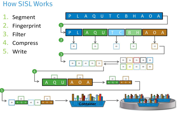
EMC Data Domain SISL™ Scaling Architecture:

SISL architecture helps to speed up Data Domain systems.

s1

SISL does the following:

 1.Segment The data is broken into variable-length segments.

 2.Fingerprint Each segment is given a fingerprint, or hash, for identification.

 3.Filter The summary vector and segment locality techniques identify 99% of the duplicate segments in RAM, inline, before storing to disk. If a segment is a duplicate, it is referenced and discarded. If a segment is new, the data moves on to step 4.

 4.Compress New segments are grouped and compressed using common algorithms: lz, gz, gzfast (lz by default).

 5.Write Writes data (segments, fingerprints, metadata and logs) to containers, and containers are written to disk.

 EMC Data Domain Data Invulnerability Architecture (DIA):

The EMC Data Domain operating system (DD OS) is built for data protection. Its elements comprise an architectural design whose goal is data invulnerability. Four technologies within the DIA fight data loss:

 End-to-end verification

  1. Fault avoidance and containment
  2. Continuous fault detection and healing
  3. File system recoverability

 Now let’s discuss on above technologies

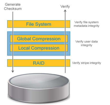
 1. End to End verification:

 e1

Steps involved in End to End Verification:

  1. Write request comes from backup software.
  2. Analyze the Data for redundancy.
  3. Store New Data Segments only.
  4. Store fingerprints and verify.
  5. Verify after Backup that DD OS can read the data from disk through Data domain File system.
  6. Verify that checksum are correct.

 2. Fault avoidance and containment

 Data Domain systems are equipped with a specialized log-structured file system that has below features.


  1. New data never overwrites existing data.
  2. Fewer complex data structures.
  3. System includes non-volatile RAM (NVRAM) for fast, safe restart.

3. Continuous fault detection and healing

 Continuous fault detection and healing provide an extra level of protection within the Data Domain operating system. The DD OS detects faults and recovers from them continuously. Continuous fault detection and healing ensures successful data restore operations.

 Continuous fault detection and healing process:

 1. The Data Domain system periodically rechecks the integrity of the RAID stripes and container logs.

 2. The Data Domain system uses RAID system redundancy to heal faults. RAID 6 is the foundation for Data Domain systems continuous fault detection and healing. Its dual-parity architecture offers advantages over conventional architectures, including RAID 1 (mirroring), RAID 3, RAID 4 or RAID 5 single-parity approaches.

 RAID 6:

Protects against two disk failures.

Protects against disk read errors during reconstruction.

Protects against the operator pulling the wrong disk.

Guarantees RAID stripe consistency even during power failure without reliance on NVRAM or an uninterruptable power supply (UPS).

 3. During every read, data integrity is re-verified.

 4. Any errors are healed as they are encountered.

 4. File system recoverability

 File system recovery is a feature that reconstructs lost or corrupted file system metadata.

In Data Domain file systems data is written in a self-describing format the file system can be recreated by scanning the logs and rebuilding it from metadata stored with the data.

 Why to Use Data Domain system?

Data Domain has below advantages

  1. Data Deduplication
  2. Easy Integration
  3. Network Efficient Replication
  4. Safe and reliable