SRDF Replication Initial Setup

Step 1: Create Source Device group

Identify the source and target device needed to perform Remote replication. It can be found using command “syminq” or “symrdf list pd”

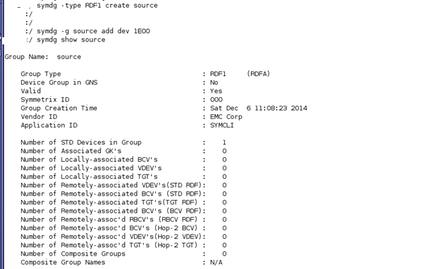
Create a Device group using command “ symdg create ‘DG Name’ –type RDF1” Type is important while creating a device group. Add the device which needs to be replicated using command “symdg –g ‘DG Name’ add dev “Device Id”

image001

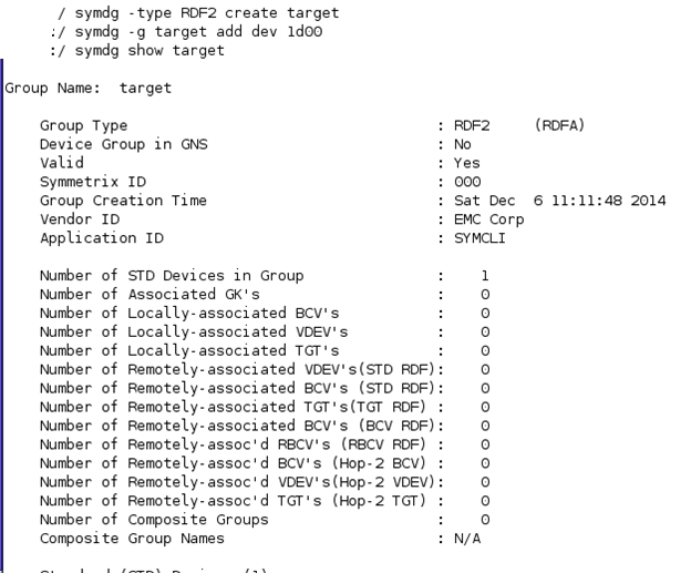
Step 2: Similarly Create Target Device group type attribute will be RDF2

image002

Step 3: Based on the requirement, Logical name for the device can be changed.

image003

image004

Prerequisite for configuring SRDF operation.

For initial configuration RDF group needs to be created. Below is the command to create a RDF group.

“symrdf addgrp -label rdfg<RDF Group#1> -sid <local sid> -remote_sid <remote sid> -dir <local RA 1>,<local RA 2> –remote_dir <remote RA 1>,<remote RA 2> -rdfg <RDF Group#1> -remote_rdfg <REMOTE_GROUP#1>”

To verify the RDF group use the below command.

“symcfg –rdfg all –sid <local sid> list”

image005

Step 4:  Create a text file and add the source and target device needs to be replicated and perform Dynamic pair creation.

image006

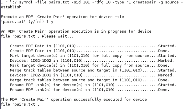
Pair can be created using below command.

“symrdf -file pair.txt -sid <local sid> -rdfg <local RDF GROUP#1> -type r1 -establish -g dg<SGN> createpair”

image007

Pair status can be checked using command symrdf –g dg_name query “ the status will be that pair has been created.

 image008

Step 5: As per the requirement the modes can be set as Synchronous or Asynchronous and replication will get configured between devices.

Command to set mode:

“symrdf –g dg<SGN> set mode async –nop “

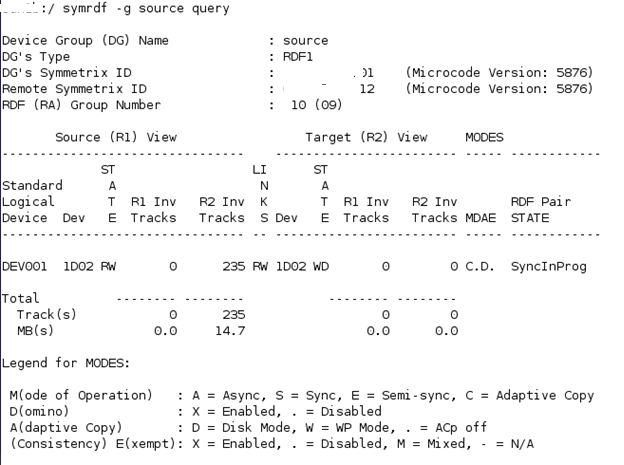
In most of the environment to copy the Invalid tracks  from R1 to R2 device mode will be set to acp_wp or acp_disk and later mode can be changed to Asynchronous mode.

image009

The status of pair will in SyncInProg when changed to acp_disk.

image010

This is the basic operations in SRDF configuration. In my next blog i will explain about SRDF disaster recovery and decision support operations.

EMC Time Finder VP SNAP

Step 1:  Identify source and Target device needed for performing TimeFinder VP SNAP. Create  a device group and add the source and target device to the group. The device which will become a target device must be specified by option ‘-tgt’. Below Screenshot explains how to create a Device group.

image001

Step 2:  Create a SNAP VP session between the source and target device. We have to use ‘-vse’ to enable SNAP VP feature in symclone command. While creating a relationship between source and target device we are using logical device name of the device 1E04(source) and 1E05(Target). image002Step 3: Query the device group vpsnap1, we can see the relationship being created.

image003

Step 4: Now activate  the VP Snap sessions. using activate command.

image004

Note: -consistent enable EMC Enginuity Consistency Assist assisted SNAP VP session. When clone sessions are activated this feature will enable consistent point in time copies of the source device.

Step 5: Once the Clone sessions gets activated the Pairs goes in to state copy on write and point in time image gets created.

image005

Percentage of copy sessions can be seen in the symclone query command. Check the copy percentage it shows 1%.

image006

Step 6: We can see the Thin pool details to check how much shared tracks are made will performing the Timefinder VP snap.

image007

Step 7: Terminate the Symclone session to stop the symclone session.image08

FAST VP Implementation

Fully Automated Storage Tiering:

FAST allows administrator to define policies and automate the movement of Luns between the Tiers based on the priority.

Advantage of FAST:

  1. Based on the load the Luns can be placed to High performance Storage tiers EFD.
  2. Low Used storages are moved to SATA disk group.

Storage Tiers: Collection of same type of storage.

There are 3 Kind of storage tiers available in VMAX:

  1. EFD
  2. FC
  3. SATA

VNX contains 3 types of storage Tiers:

  1. EFD
  2. SAS
  3. NL SAS

We won’t focus on FAST implementation for Thick devices because now a days provisioning of Thick devices are not advised.

FAST VP:

FAST VP is used for the implementation of FAST in Virtual provisioning.

fast TierLet’s see How FAST VP works:

  1. There will be Thin devices being created and allocated to a certain FAST policy.
  2. Based on the FAST policy defined the highly utilized data from Sub Lun levels are identified.
  3. Sub Lun highly utilized are moved to Storage Tier Flash.
  4. Sub Lun underutilized are moved to SATA storage Tier.
  5. The FAST VP will identify highly utilized Sub Luns based on the Symmetrix Microcode and FAST controller.

Components of FAST VP:

Comp

Components description:

EMC Symmetrix has two components one is Microcode which resided in Symmetrix Operating system and other is FAST controller residing in Service process.

  1. Performance Data Collection:

Constant performance and CPU utilization of Thin Luns are determined in Sub Lun Levels.

  1. Performance Data Analysis:

Performance data collected are analyzed in the FAST controller.

  1. Intelligent Tiering Algorithm:

Data collected through Micro code and Analysis report generated by FAST controller are used by Intelligent Tiering Algorithm to issue a Sub Lun movement to VLUN VP data Movement Engine.

  1. Allocation Compliance algorithm:

Enforces upper limit of Storage Tier can be used for Sub Lun Data Movement for each Storage groups.

  1. VLUN VP Data Movement Engine:

Based on the Intelligent Tiering algorithm the Extent of data are moved between Tiers.

FAST VP has two modes of operation:

  1. Automatic: Data Movement and Data Analysis are continuously performed.
  2. Off Mode: Only performance statistics will be collected, No data movements will take place.

Elements of FAST VP:

tier

Storage Tier:

Collection of drive technology like EFD, FC, SATA.

Storage Group:

Collection of host accessible devices.

FAST Policy:

Percentage of storage capacity between the storage tiers can be used by storage group.

Control Parameters for FAST VP:

  1. Movement Mode: Automatic or Off
  2. Relocation rate: Amount of data that can be moved at a Time. They are measured from 1 to 10, Default value is 5; 1 is the highest value and 10 is the lowest value.
  3. Reserved capacity Limit: Percentage of Virtual pool reserved for Non FAST activity. If we reach this level then FAST movement will not be performed.
  4. Workload analysis time: Amount of work load analysis samples to be collected.
  5. Initial period: Minimum amount of work load analysis needs to be completed before analyzing the sample.

Sample FAST VP control Parameters:
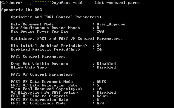
control

Time Windows for FAST VP:

  1. Performance Time Window:

Collecting performance data 24×7. This time window can be changed but not recommended by EMC.

  1. Move Time window:

Time window during which sub Luns can be moved.

FAST implementation steps:

  1. Enable FAST VP.
  2. Set Control Parameters.
  3. Create Storage Tier.
  4. Create FAST Policy.
  5. Associate storage group to FAST Policy.
  6. Enable Time Windows setting.

Pre Checks:

Check for FAST VP licenses:

License can be checked using below command:

Symlmf list –type emclm –sid XXX

Always check with EMC before implementing FAST VP and get the suggestion for control parameters setting and time windows setting.

  1. Enable FAST VP:

Command to enable FAST VP.

Symfast –sid XX enable –vp

To List the states of FAST VP:

Symfast –sid XX list –state

  1. Set Control Parameters settings:

To List control parameters:

Symfast –sid xxx list –control_parms

To change control parameters setting:

symfast -sid XXX set -control_parms -mode AUTO_APPROVE -max_simult_devs 8 -max_devs 240 -min_perf_period 2 -workload_period 24 -vp_data_move_mode AUTO -vp_reloc_rate 5 -pool_resv_cap 20 -vp_allocation_by_fp disable

  1. Create Storage Tier:

Symtier is the command used for creating Storage tier.

RAID protection for Tier creation:

RAID 0 = -tgt_unprotected 
RAID 1 = -tgt_raid1 
RAID 5 = -tgt_raid5 -tgt_prot 3+1, -tgt_raid5 -tgt_prot 7+1
RAID 6 = -tgt_raid6 -tgt_prot 6+2 , -tgt_raid6 -tgt_prot 14+2

We had already created three pools named EFD,FC,SATA.

Creating EFD Tier:

symtier -sid xxx create -name EFD_VP_Tier -tgt_raid5 -tgt_prot 7+1 -technology EFD -vp -pool PoolName –EFD

 Creating FC Tier:

 symtier -sid xxx create -name FC_VP_Tier -tgt_raid5 -tgt_prot 3+1 -technology FC  -vp -pool PoolName –FC

 Creating SATA Tier:

 symtier -sid xxx create -name FC_SATA_Tier -tgt_rai6 -tgt_prot 6+2 -technology SATA  -vp -pool PoolName –SATA

 To List Tiers:

Symfast –sid XXX list

1

4. Create FAST Policy:

Create FAST VP policy.

symfast -sid xxx -fp create -name EFD_VP

Add Storage Tiers to FAST Policy.

symfast -sid xxx -fp add -tier_name EFD_VP_Tier  -max_sg_percent 100 -fp_name EFD_VP

symfast -sid xxx -fp add -tier_name FC_VP_Tier -max_sg_percent 20 -fp_name EFD_VP

symfast -sid xxx -fp add -tier_name SATA_VP_Tier -max_sg_percent 10 -fp_name EFD_VP

Maximum 300% for Storage tier can be allocated to a FAST Policy.

To list FAST VP policy:

Symfast list –sid 606 –fp -vp


2

5. Associate storage group to FAST Policy:

Storage groups will be created while Auto provisioning for a host.

Associate a Storage group to a FAST policy.

symfast -sid xxx associate -sg Storage_group -fp_name EFD_VP -priority 2 

Storage group associated with fast policy will be assigned a priority between 1 to3. 1 is highest, 3 is lowest and 2 is default priority. 

To List association: 

symfast -sid xxx list –association 

6. Enable Time Windows setting: 

To List Time window:

Symtw list –sid XXX

To Change the Move Time Window setting: 

symtw -sid XXX add -type MOVE_VP -days mon,tue,wed,thu,fri,sat,sun -start_time 18:00 -end_time 24:00 –inclusive

 To Change performance Time Window:

symtw -sid xxx -inclusive -type perf add -days Mon,Tue,Wed,Thu,Fri,Sat,Sun -start_time 00:00 -end_time 24:00

Mostly Performance time windows are not changed. Default time windows are preferred for performance time window setting.
Meta Device concept and Syntax

Meta device: Symmetrix mechanism for defining a device larger than the current maximum hyper-volume size. You can concatenate existing devices to form a larger meta device that is presented to the host as a single addressable device.

Meta

Two kinds of meta devices:

 Concatenated:

In Concatenated Device the Data processing will happen to Meta Head once Meta head gets full data processing moves to next Meta member.

 Striped:

Striped meta device data on meta members is addressed in user-defined stripes or chunks instead of filling an entire volume first before addressing the next volume.

 Syntax to create Meta Device:

 Metadevices can be created in either be formed using symconfigure or they can be automatically created using Solutions Enabler 6.5.1 or higher.

 form meta from dev SymDevName, config=MetaOption

[, stripe_size=<MetaStripeSize>[cyl]]

[, count=<member_count>];

 To add members to Meta:

 Add dev XXXX to meta XXXX

Dissolving Meta:

For dissolving Meta below mentioned steps must be followed.

  1. Unmap Meta device.
  2. Remove Meta head.
  3. Free up meta Members.

Syntax for dissolving Meta:

Dissolve meta dev XXXX

Creation of Different Devices

What is Hypers?

Symmetrix physical disks are split into logical Hyper Volumes. Hyper Volumes (disk slices) are then defined as Symmetrix Logical Volumes (SLV). SLVs are internally labeled with hexadecimal identifiers (0000-FFFF). The maximum number of host addressable logical volumes per Symmetrix configuration is 64,000.

Volume Table of Contents (VTOC) on disk are used to map logical volumes to physical disks. These data structures are created during initial installation.

  • Maximum hyper volumes per physical disk varies with software version – 512 with 5874 and 1024 with 5875+
  • Hyper volumes can be of variable size

Hyper

Common Device Types:

  1. 2-Way_mir, RAID-1, RAID-5 or RAID-6 protection
  2. Gatekeeper devices.
  3. BCVs are device types that are used for local replication.
  4. RDF volumes are used for remote replication.
  5. Virtual devices are used in TimeFinder/Snap. They are cache only devices and do not consume disk space.
  6. Thin Devices are used for Virtual provisioning. They are cache only devices and do not consume disk space.
  7. Diskless devices are used for cascaded R21s. They are cache only devices and do not consume disk space.
  8. Save and Data devices hold the actual data for Virtual and Thin devices respectively.

Each devices can be created with configuration manager.

There are more types of devices that can be created. Please refer Symmetrix array controls guide for more details.

Device creation Examples

  1. 2-Way-Mir

 Symconfigure  -sid XXX –cmd “ create device count=4,size=1200 cyl, config=2-Way-Mir,emulation=FBA,disk_group=1;” commit

  1. RAID 5

 Symconfigure  -sid XXX –cmd “ create device count=4,size=1200 cyl, config=RAID-5,data_member_count=7,emulation=FBA, disk_group=1;” commit

  1. VDEV

Symconfigure  -sid XXX –cmd “ create device count=4,size=1200 cyl, config=VDEV, emulation=FBA” commit 

  1. Save device

 Symconfigure  -sid XXX –cmd “ create device count=4,size=1200 cyl, config=RAID-6,data_member_count=6,emulation=FBA, disk_group=1,attribute=savedev;” commit

Note: Save device, Data Device needs to have attribute specified.

  1. Dynamic RDF capable device

 Symconfigure  -sid XXX –cmd “ create device count=4,size=1200 cyl, config=RAID-6,data_member_count=6,emulation=FBA, disk_group=1,dynamic_capability=dyn_rdf;” commit

Special device called Gatekeeper. What is it and why needed?

Gatekeeper is not intended to store data and is usually configured as a small device up to 3 cylinders. Gatekeeper devices are LUNs that act as the target of command requests to Enginuity. The more commands that are issued from the host, and the more complex the actions required by those commands, the more gatekeepers that are required to handle those requests in a timely manner.

When Solutions Enabler successfully obtains a gatekeeper, it locks the device, and then processes the system commands. Once Solutions Enabler has processed the system commands, it closes and unlocks the device, freeing it for other processing.

When selecting a gatekeeper, Solutions Enabler starts with the highest priority gatekeeper candidate as described below. If there are no gatekeeper candidates at that priority, or the device is not accessible or currently in use, then Solutions Enabler tries to use the remaining gatekeeper candidates, in priority order, until it successfully obtains a gatekeeper, or it has tried all gatekeeper candidates. The gatekeeper selection priority is as follows:

1.Small (under 10 cylinder devices)

2.Standard non-RDF and non-metadevices

3.RDF R1 devices

4.RDF R2 devices

5.ACLX devices

Command to create Gatekeeper:

Symconfigure  -sid XXX –cmd “Create gatekeeper count=3,emulation=FBA,type=thin;” commit

Virtual Provisioning Concepts

Virtual Provisioning

Concept of Virtual Provisioning VP:

In VP we will first create a thin pool and then the Data Device is added to the thin pool. If we need to allocate a Device to Host then we create a Thin device and bound to the Thin Pool already created.

Benefits of Virtual Provisioning:

  1. Capacity utilization gets improved
  2. Ease and speedy provisioning of storage
  3. Pool Based View

Virtual provisioning Components:

  1. Thin Device(TDEV)
  2. Thin Pool
  3. Data Device(TDAT)

Terms to be known:

Symmetrix Virtual Provisioning: Also known in the industry as “thin provisioning”, is the ability to present a host and therefore an application, with more storage capacity than is physically allocated to it in the storage array. The physical storage is then allocated to the application “on-demand” as it is needed from a shared pool of storage.

Over-subscription: where the total capacity of all TDEVs bound to a thin pool is greater than the aggregate capacity of all data devices in the pool.

Thin Device:  Consumes no disk space consist of data structures in Cache. Initial allocation of 768 KB is done when bound to Thin Pool. Thin device supports FBA and CKD; TDEV can be replicated using Symmetrix Local and remote Replication..

Thin pools: Contain the aggregate available space that is available for a set of thin devices.

A pool can contain zero or more data devices and can be created in a separate operation or at the time that the data devices are created. When a device is added to a pool it can be enabled for allocation or disabled for future use.

Data Device: Data Device is not visible to the host and must be contained in a pool before they can be used. Thin pools can only contain devices of the same emulation and protection type. It is not a recommendation to have same type of Data device in thin pool, but best practice is to have same Type of data Device.


Host Writes and reads from Thin Device?

This concept is only for VMAX, Hitachi and other vendor have different concepts for read and writes.

Writes to Thin Device:

  • Initially when Thin device gets bounded to Thin pool 1 Extent is allocated to thin pool.
  • Each Host write I/O is written as extent to Thin Pool data device in round robin Manner.
  • 1 extent=12*64KB=768KB.

Reads to Thin Device:

A thin device is seen by the host like any other device. Normally an application will only read storage that was previously written to. However, if the host reads a block that was not previously written to, the Symmetrix returns data blocks that contain all zeroes.

Let’s see a Virtual provisioning with solution enabler example. Below mentioned process was tried by me in Test environment.

Steps Involved in Virtual Provisioning:

  1. Planning how much capacity of thin pools needed for virtual provisioning.

    2. create a Thin Device

 Symconfigure –sid XXX –cmd “ create device count=8, size=1150 cyl, config=TDEV,emulation=FBA;” commit

 To Display freeThin Device:

Symdev list –pd –tdev -unbound

    3. Create a Data Device

 Symconfigure –sid XXX –cmd “ create device count=20, size=262144 cyl, config=2-way-mir,emulation=FBA,attribute=datadev;” commit

 To diplay data devices:

 Symdev list –datadev

 Note: Data Devices will be attributed as datadev. Data  devices cannot be used for thick provisioning.

     4. Create a Thin Pool

 Symconfigure –sid XXX –cmd “create pool Pool_name type=thin;” commit

    5.Add Data devices to Thin Pool

Symconfigure –sid XXX –cmd “add dev 12EF:2E2F to pool Pool_name type=thin,member_state=ENABLE;” commit

  1. Bind Thin Device to Thin Pool

 Symconfigure –sid XXX –cmd “ bind tdev 012F:12EF to pool Pool_name;” commit

 Now the Thin device can be provisioned to Host using Auto provisioning.


EMC VMAX Storage Provisioning concepts with Examples

Note: For Provisioning Storage First the Host needs to be zoned with Storage.

Terms to be Known:

SID: Symmetrix ID

Device: In Vmax device are LUN

Emulation: There are two kind of Emulation Available in VMAX FBA and CKD.

FBA: Fixed block Architecture used for open systems.

CKD: Count key data used for Mainframes and it is a IBM Technology.

Cylinders: Unit to measure capacity in Storage.

1 CYL= 0.9375 MB

Size in GB= Number of Cylinders x 15 x 128 x 512 / 1024 / 1024 / 1024

Number of Cylinders= Size in GB / 15 / 128 / 512 x 1024 x 1024 x 1024

Size of one Sector: 512 Bytes

Number of Sectors per Track: 128

Number of Heads: 15

Size of One Track: ( 512 x 128 )

Bytes Size of One Cylinder: ( 512 x 128 x 15 ) Bytes

Pre-check Needed to be performed when provisioning storage in VMAX

1. Verify that the current Symmetrix configuration is a viable configuration for host-initiated configuration changes. The command

“symconfigure verify -sid SymmID”

will return successfully if the Symmetrix is ready for configuration changes.

2. Check Free physical disk space for carving Device in VMAX.

“symconfigure list -freespace [-units CYLINDERS|MB] -sid SymmID”

To Check Thin Pool freespace.

“symcfg -sid XXX list -thin -pool -GB -detail”

Auto provisioning Concept:

Auto Provisioning contains 3 Groups.

1. Initiator Group

2. Port Group

3. Storage Group

Initiator Group contains the world wide name or iSCSI name of a host initiator, also referred to as an HBA or host bus adapter. An initiator group may contain a combination of up to thirty-two, Fibre Channel initiators or eight, iSCSI names or a combination of both. Port flags are set on an initiator group basis, with one set of port flags applying to all initiators in the group. An individual initiator can only belong to one Initiator Group. The group can be a member in another initiator group. It can be grouped within a group. This feature is called cascaded initiator groups, and is only allowed to a cascaded level of one.

Port Group may contain any number of valid front end ports, FAs. Front end ports may belong to more than one port group. Before a port can be added to a port group the ACLX flag must enabled on the port.

Storage Group may contain up to  (4,096) Symmetrix logical volumes. A logical volume may belong to more than one storage group. There is a limit of  (8,192) storage groups.

Masking view is a container of a storage group, a port group, and an initiator group. When you create a masking view, the devices in the storage group become visible to the host. The devices are masked and mapped automatically.

Step 1: Creation of Device 

symconfigure -sid xxx -cmd “create dev count=1, size=12000 CYL, emulation=FBA, config=TDEV, binding to pool=Thin Pool Name preallocate size=12000 CYL;” commit

Now a days most of the devices created are Thin Device, Above is command to create Thin device. Preallocate Size needs to be specified as ALL if total capacity needs to be allocated to Host

Step 2: Creation of Initiator Group

Create Initiator group

Command: symaccess -sid XXX create -name Init_server -type initiator -consistent_lun

-consistent_lun option if the devices of a storage group (in a view) need to be seen on the same LUN on all ports of the port group). If the -consistent_lun option is set on the initiator group, Solutions Enabler will make sure that the LUN number assigned to devices is the same for the ports. If this is not set, then the first available LUN on each individual port will be chosen.

Add the initiators to the IG

symaccess -sid XXX -name Init_server -type initiator -wwn 10000xxxxxxxxxxxx add

symaccess -sid XXX -name Init_server -type initiator -wwn 10000xxxxxxxxxxxx add

Rename Initiator Aliases

symaccess -sid XXX rename -wwn 10000xxxxxxxxxxxx -alias Server/HBA1

symaccess -sid XXX rename -wwn 10000xxxxxxxxxxxx -alias Server/HBA1

Set portflag settings on IG

symaccess -sid 551 -name Init_server -type initiator set ig_flags on SC2,SCSI3,OS2007 -enable

Port Flags needed to be set at Initiator group as per host requirement.

To Show the configuration :symaccess -sid XXX show Init_server -type initiator

Step 3: Creation of  Port group

Command: symaccess -sid XXX create -name Port_server -type port -dirport 8G:0,9G:0

To Show the configuration : symaccess -sid XXX show Port_server -type port

Step 4: Creation of Storage Group

symaccess -sid XXX create -name Storage_server -type storage

Add the storage to the storage group which was initially created.

symaccess -sid XXX -name Storage_server  -type storage add devs 2E9F

To Show the configuration : symaccess -sid XXX show Storage_server -type storage

Step 5: Create the Masking View

symaccess -sid XXX create view -name View_server -sg Storage_server -pg Port_server -ig init_server

To Show the configuration : symaccess -sid 551 list view -name View_server -detail

Scan from Host end to view the Device allocated to the Host

EMC VMAX Architecture

EMC VMAX Architecture

Currently there are 3 types of EMC Vmax available EMC Vmax 10K,EMCVmax 20K and EMC Vmax 40K.This article describing the general architecture of Vmax models.

Symmetrix Vmax is EMC’s prestigious product.Compared to the previous models, Vmax has been optimized for increased availability,performance and capacity utilization on all tiers with all RAID types.Vmax’s enhanced device configuration and replication operations results in easier,faster and more efficient management of large virtual and physical environment.

The main architectural difference between DMX and Vmax model is that vmax has engineconcept.In DMX model,we have different hardware for front end(FA director),back end(DA director) and memory modules.But in Vmax all these hardwares are integrated together and is knows as Vmax Engine.

A EMC Vmax storage array support from 1 to maximum of 8 Vmaxengines.Each of these engines contains two symmetrixvmax directors.

Each director includes

 8 multi-core CPUs (total 16 per engine)

– Cache memory(global memory)

– Front end I/O modules

– Back end I/O modules

– System Interface Module(SIB)

Apart from this,each engine has redundant power supplies,coolingfans,standby power supplies(SPS) and environmental modules.All these engines are interconnected usingVmax Matrix Interface Board Enclosure(MIBE).Each director has two connection to MIBE via system interface module(SIB) ports as shown below.

Multi-core CPUs:

Multi-Core CPUs deliver new levels of performance and functionality in a smaller footprint with reduced power and cooling requirements.Each director has 8 multi core CPUs and a total of 16 CPUs per engine.

Cache memory(global memory):

Each director can be configured with 16, 32 or 64 GB of physical memory. Of this, a small portion (4 GB) is reserved for local processing, and the rest constitutes Global Memory. Global Memory on any given director is always mirrored to another director in the system.So the minimum usable memory will be 16 GB(total 32GB, on a single engine configuration) and maximum will be 512GB (total 1024GB,fully loaded eight VMAX Engines system)

Memory is accessible by any director within the system:
1. If a system has a single VMAX Engine, physical memory mirrors are internal to the enclosure.
2. If a system has multiple VMAX Engines, physical memory mirrors are provided between enclosures.

Front End I/O Module :

Front end modules are used for host connectivity.Host connectivity via Fibre Channel, iSCSI and FICON are supported.

Back End I/O Module :

Back end module provide access to the disk drives.Disks drives are configured under these I/O modules.

System Interface Module(SIB):

SIBs are responsible for interconnecting the Vmax engine’s directors through  Matrix Interface Board Enclosure(MIBE).Each Vmax engine has two SIBs and each has two ports.

Matrix Interface Board Enclosure(MIBE): 

Director port connection to MIBE.

Mibe connection
Similar to DMX3 and DMX4 arrays,Vmax has two types of bays

  1. System bay :

System bay contains all Vmaxengines.Apart from Vmaxengines,it contains system bay standby power supplies(SPS), Uninterrupted Power Supply(UPS),Matrix Interface Board Enclosure (MIBE), and a Server (Service Processor) with Keyboard- Video-Mouse (KVM) assembly.

  1. Storage bay :

The Symmetrix V-Max array Storage Bay is similar to the Storage Bay of the DMX-3 and DMX-4 systems. It consists of eight to sixteen Drive Enclosures, 48 to 240 drives, eight (8) SPS modules, and unique cabling when compared with the DMX Series. The Symmetrix V-Max array Storage Bay is configured with capacities of up to 120 disk drives for a half populated bay or 240 disk drives for a fully populated bay. Drives, LCCs, power supplies, and blower modules are fully redundant and hot swappable and are enclosed inside Disk Array Enclosure(DAE).One DAE holds 15 physical disk drives and one storage bay has total 16 DAEs(hence a storage bay has maximum of 240 disk, 16*15)

Please find the link containing detailed Architecture. EMC VMAX Architecture