Hitachi VSP Architecture

VSAP di

Overview

The VSP is enterprise storage array that scales from a single bay up to a maximum of 6 bays.  The two central bays house what Hitachi is calling Control Chassis (containing processors, memory, front and backend connectivity) as well as drive enclosures.  The remaining 4 bays can contain only drive enclosures (Max 2048 Drives).

vsp1

  1. It comes in a standard sized 42u 19 inch rack
  2. Has a hot and cold isle airflow design
  3. Can take power feeds from above or below – you can now install one in your garage without installing a raised floor.

vsp2

Sub-LUN Tiering

Hitachi Dynamic Tiering (HDT).

  1. All drives can be placed into a single tiering pool.  SSD, SAS and SATA into a Single tier Pool.
  2. New data is staged to the highest tieravailable, and then, as it becomes less active it is migrated down the tiers.
  3. The Sub-LUN extent size42 MB- VSP will move data up and down the tiers in units of 42MB (contiguous space).
  4. On the policy side of things, you can set gathering windows, exclusion windows, and the movement cycle is between 1-24 hours.

SAS backend and 2.5 inch drives

SAS and 2.5 inch drives are supported in VSP

Backend

Front End Director (FED) Design

Data Accelerator ASICs

The FEDs and BEDs have custom I/O routing ASICs that are specialised for I/O traffic management. These ASICs have an affinity with ports and CPU’s are no longer locked to a particular ports all ports are moved to a processor complex called the Virtual Storage Director (VSD) where ports are pooled and can have their resources dynamically assigned and un-assigned from any front or back end port.

Control Chassis (Logic Boxes)

Control Chassis are two(Control Chassis 0 and Control Chassis 1)

The picture below is of the front and rear of a frame containing a Control Chassis.  The Control Chassis is in the bottom half on both pictures; the top half contains the drive enclosures hidden by fans.

vsp

At the front there are 4 x Virtual Storage Directors (VSD), and 8 x Data Cache Directors and at the rear there are 8 x FEDs, 4 x BEDs, and 8 x Grid Switches, or GSW.

vsp4

Data cache is backed up to onboard flash drives,Each BED has 8 x 6Gbps SAS paths.  That adds up to 32 backend SAS links per Control Chassis, and 64 x 6Gbps links in a fully configured unit.  SAS runs at full duplex.

vsp5

Control Memory (CM) is located on the Virtual Storage Directors alongside the general purpose CPUs making it very quickly accessible to the CPUs, like an L2 cache.  As with previous architectures, Control Memory stores the usual metadata and system state such as LDEV mappings, DIF tables, run tables etc.

Grid Switches – The Grid Switch boards provide the, 4-lane PCIe gen. 1, paths that cross connect all of the other boards. Each Control Chassis can have either two or four GSW boards. Each GSW board has 24 unidirectional ports, each port having a send and receive path, with each operating at 1024MB/s.Hitachi refers to the Control Chassis as being tightly coupled, and the interconnect between the two is PCIe gen 1 over copper.  The Control Chassi are able to communicate by mapping Hi-Star over PCIe.

vsp 6.jpg


IBM SVC Storage Provisioning

Create Host

svctask mkhost -name Host name -hbawwpn Host WWN -iogrp 0 -force -mask 1111

Create Host

Add port to Host

svctask addhostport –hbawwpn wwn [-force] host-name/host-id

Delete port to Host

svctask rmhostport –hbawwpn wwn [-force] host-name/host-id

Create Vdisk(Lun) for host

  1. check what is the mdisk group(Storage pool Id) using command “svcinfo lsmdiskgrp”

2. check the IOgroup details using command “svcinfo lsiogrp”

3. Cretae Vdisk

svctask mkvdisk -mdiskgrp mdiskgroupid -iogrp 1 -size 1024 -unit gb -name Vdisk name

Create Volume

Map Vdisk to host

svctask mkvdiskhostmap -force -host [host-id ; host_name] -scsi [lun_id] vdisk_name ; vdisk_id

Mapping Volume


Brocade useful Commands

Show Commands

Command Description
nodefind wwn

psshow

To find whether WWN loggedin array

Displays the status of the power supply

fansshow Displays the status of the fans
tempshow Displays the status of the temperature readings
sensorshow Displays the status of the sensor readings
nsshow Displays information in the name server
nsshow -t Displays information in the name server
nsshow -r Displays the information in the name server along with the state change registration details
nscamshow Displays detailed information of all the devices connected to all the switches in the fabric (Remote Name Servers)
nsallshow Displays the 24 bit address of all devices that are in the fabric
licenseshow Displays all the licenses that have been added in the switch
date Displays the current date set on the switch
bannershow Displays the banner that will appear when logging in unsing the CLI or webtools
httpcfgshow Displays the JAVA version the switch expects at the management console
switchname Displays the switchname
fabricshow Displays information of all the switches in the fabric
userconfig –show -a Displays the account information like role , description , password exp date , locked status
switchstatusshow Displays the overall status of the switch
switchstatuspolicyshow Displays policy set for the switch regarding Marginal(Yellow) or Down(Red) error status
portshow To show the port status
portcfgshow Displays the speed set for all ports on all slots and other detailed port information
configshow fabric.ops Displays the parameters of the switch. Ensure all switches in a fabric have the same parameters in order to communicate
configshow fabric.ops.pidFormat Displays the PID set for a switch Core , Native or Extended edge
switchuptime OR uptime Displays the uptime for the switch
firmwareshow Displays the firmware on the switch
version Displays the current firmware version on the switch
hashow Displays the status of local and remote CP’s. High availability , heartbeat and synchronization

Port Settings

Command Description
portcfgshow Displays the port settings
portcfg rscnsupr [slot/port] –enable A registered state change registration is suppressed when a state change occurs on the port
portcfg rscnsupr [slot/port] –disable A registered state change registration is sent when a state change occurs on the port
portname To assign a name for a port
portdisable To disable a port or slot
portenable To enable a port or slot
portcfgpersistentdisable To disable a port , status would not change even after rebooting the switch
portcfgpersistentenable To enable a port , status would not change even after rebooting the switch
portshow To show the port status
portcfgspeed , To set speed for a port Note – 0:auto negotiated 1,2,4 Gbit/sec , 1 : 1Gbit/sec , 2 : 2 Gbit/sec , 4 : 4Gbit/sec
switchcfgspeed To set speed for all the ports on the switch Note – 0:auto negotiated 1,2,4 Gbit/sec , 1 : 1Gbit/sec , 2 : 2 Gbit/sec , 4 : 4Gbit/sec
portcfgshow Displays the speed set for all ports on all slots and other detailed port information
portcfgdefault To set the port settings to default
portcfglongdistance To set the long distance mode . Default is L0(Normal), as per distance will display LE <=10 kms , L0.5 <=25kms , L1 <=50 kms, L2<=100kms , LD=auto , LS = Static
portcfgeport Used to disable a port from being a E port

Setting commands

Command Description
ipaddrset To set the ip address for the switch
bannerset To set the banner which will appear when logging in using the CLI or webtools

Time and Date Settings

Command Description
date Displays the current date set on the switch
tsclockserver 10.10.1.1 Instruction for the principal switch to synchronize time with the NTP server (specify ipaddress of the NTP server)
tsclockserver LOCL Instruction to stop NTP server synchronization (Local time of the switch)
date mmddhhmmyy To set the time of the switch when the NTP server synchronization is cancelled
tstimezone -5 To set the time zone for individual switches

License Commands

Command Description
licenseshow Displays all the licenses that are added in the switch
licenseadd To add a new license to the switch
licenseremove To remove a license from the switch
licenseidshow Based on Switch WWN

Banner Commands

Command Description
bannershow Displays the banner that will appear when logging in unsing the CLI or webtools
bannerset To set the banner which will appear when logging in using the CLI or webtools
bannerset “” To remove the bannerset

Password commands

Command Description
passwd To change the password for that particular login
passwdcfg –set -lowercase 3 uppercase 1 -digits 2 -punctuation 2 -minlength 10 -history 3 To set the password rules
passwdcfg –set -minpasswordage 1 To set the minimum password age in Days
passwdcfg –set -maxpasswordage 30 To set the maximum password age in Days
passwdcfg –set -warning 23 To set a warning for the expiration Days remaining
passwdcfg –set -lockoutthreshold 5 To set the account lockout thresh hold
passwdcfg –set -lockoutduration 30 To set the account lockout duration in Minutes
passwdcfg –setdefault To restore the password policy to Factory settings (min length – 8, history -1 , lockoutduration – 30)

User Configuration (commands to administer Accounts)

Command Description
userconfig –show -a / userconfig –show Displays all the account information like role , description , password exp date , locked status
userconfig –add jdoe -r admin -d “Jane Doe” To add a new account -r = role , -d = description
userconfig –show jdoe Displays all the information for the account jdoe
userconfig –change -e no To Disable an account , usually default a/cs like admin and user . But ensure before disabling the admin a/c there is another a/c with admin rights
userconfig –change -e yes To Enable an account

NPIV Commands

Command Description
portcfgnpivport Enables NPIV functionality on a port . By default on Condor based switches
configure In order to increase the no of port logins ( Default is 126 , max 255)

SNMP

Command Description
snmpconfig snmpconfig for 5.0 above fos
agtcfgset snmp config for fos below 5.0
snmpmibcapset for choosing the MIB’s for the snmp settings

Zoning

Command Description
alicreate “Name”, “domain,port no” Used to create alias
alicreate “Name”,”portname1; portname2″ To create more than one ports under one alias
alidelete “Name” To delete alias
aliadd “Name”, “domain,port no” To add additional ports to an alias
aliremove “Name”, “domain,port no” To remove a port from the alias
alishow “AliName” To show the alias configuration on the switch
zonecreate “Zone Name”, “alias1; alias2″ To create zones based on alias
zonedelete “ZoneName” To delete a zone
zoneadd “ZoneName”, “alias name” To add additional alias into the zone
zoneremove “ZoneName”, “alias name” To remove an alias from the zone
zoneshow “zoneName” To show the zone configuration information
cfgcreate “Configname”, “Zone1; Zone2″ To create configurations by adding in zones
cfgdelete “ConfigName” To delete a configuration
cfgadd “ConfigName”, “Zone3″ To add additional zones in the configuration
cfgremove “ConfigName”, “Zone3″ To remove a zone from the configuration
cfgshow “ConfigName” To show the details of that configuration
cfgenable “ConfigName” To enable a configuration on the switch
cfgsave To have the effective configuration to be written into the flash memory

Firmware commands

Command Description
configupload Saves the switch config as an ASCII text file to an FTP server
configdownload To restore a switch configuration from ASCII text file Note – Need to disable the switch before downloading the config file
configure => cfgload attributes : [y] => Ensure secure config upload / download : [y] Fabric OS v 4.4 & above provides Secure File Copy Protocol (SCP) during upload or download of configurations
firmwaredownload To download the firmware to be installed on the switch
firmwareshow To be run after installing the firmware on the switch
version Displays the current firmware version on the switch
fastboot Needs to be run after installing the firmware . This doesnot include the post
reboot Needs to be run after installing the firmware. This includes the post

Other commands

Command Description
killtelnet To kill a particular session which is using telnet
configure To configure a switch
quitemode To switch off the quietmode
quietmode 1 To suppress messages to the console
switchname Displays the switchname
switchname “EXAMPLE” To assign a switch name
configure To disable/enable TELNETD
timeout Displays the timeout time set for Telnet session on the switch
timeout 10 To set a specific timeout time for the Telnet session
switchuptime OR uptime Displays the uptime for the switch
switchcfgspeed To set speed for all the ports on the switch Note – 0:auto negotiated 1,2,4 Gbit/sec , 1 : 1Gbit/sec , 2 : 2 Gbit/sec , 4 : 4Gbit/sec
fastboot To reboot the switch without post
reboot To reboot the switch with the post
switchstatusshow Displays the overall status of the switch
switchstatuspolicyshow Displays policy set for the switch regarding Marginal(Yellow) or Down(Red) error status
switchstatuspolicyset To change the policy set for the switch regarding Marginal(Yellow) or Down(Red) error status

SRDF Replication Initial Setup

Step 1: Create Source Device group

Identify the source and target device needed to perform Remote replication. It can be found using command “syminq” or “symrdf list pd”

Create a Device group using command “ symdg create ‘DG Name’ –type RDF1” Type is important while creating a device group. Add the device which needs to be replicated using command “symdg –g ‘DG Name’ add dev “Device Id”

image001

Step 2: Similarly Create Target Device group type attribute will be RDF2

image002

Step 3: Based on the requirement, Logical name for the device can be changed.

image003

image004

Prerequisite for configuring SRDF operation.

For initial configuration RDF group needs to be created. Below is the command to create a RDF group.

“symrdf addgrp -label rdfg<RDF Group#1> -sid <local sid> -remote_sid <remote sid> -dir <local RA 1>,<local RA 2> –remote_dir <remote RA 1>,<remote RA 2> -rdfg <RDF Group#1> -remote_rdfg <REMOTE_GROUP#1>”

To verify the RDF group use the below command.

“symcfg –rdfg all –sid <local sid> list”

image005

Step 4:  Create a text file and add the source and target device needs to be replicated and perform Dynamic pair creation.

image006

Pair can be created using below command.

“symrdf -file pair.txt -sid <local sid> -rdfg <local RDF GROUP#1> -type r1 -establish -g dg<SGN> createpair”

image007

Pair status can be checked using command symrdf –g dg_name query “ the status will be that pair has been created.

 image008

Step 5: As per the requirement the modes can be set as Synchronous or Asynchronous and replication will get configured between devices.

Command to set mode:

“symrdf –g dg<SGN> set mode async –nop “

In most of the environment to copy the Invalid tracks  from R1 to R2 device mode will be set to acp_wp or acp_disk and later mode can be changed to Asynchronous mode.

image009

The status of pair will in SyncInProg when changed to acp_disk.

image010

This is the basic operations in SRDF configuration. In my next blog i will explain about SRDF disaster recovery and decision support operations.

EMC Time Finder VP SNAP

Step 1:  Identify source and Target device needed for performing TimeFinder VP SNAP. Create  a device group and add the source and target device to the group. The device which will become a target device must be specified by option ‘-tgt’. Below Screenshot explains how to create a Device group.

image001

Step 2:  Create a SNAP VP session between the source and target device. We have to use ‘-vse’ to enable SNAP VP feature in symclone command. While creating a relationship between source and target device we are using logical device name of the device 1E04(source) and 1E05(Target). image002Step 3: Query the device group vpsnap1, we can see the relationship being created.

image003

Step 4: Now activate  the VP Snap sessions. using activate command.

image004

Note: -consistent enable EMC Enginuity Consistency Assist assisted SNAP VP session. When clone sessions are activated this feature will enable consistent point in time copies of the source device.

Step 5: Once the Clone sessions gets activated the Pairs goes in to state copy on write and point in time image gets created.

image005

Percentage of copy sessions can be seen in the symclone query command. Check the copy percentage it shows 1%.

image006

Step 6: We can see the Thin pool details to check how much shared tracks are made will performing the Timefinder VP snap.

image007

Step 7: Terminate the Symclone session to stop the symclone session.image08

Interview Questions December

Data Domain:

  1. Deduplication.
  2. Inline deduplication.
  3. Source based and target based deduplication.
  4. DDBoost.
  5. License requirement.
  6. User creation in data domain.
  7. VTL.
  8. Replication and its type.
  9. Mtree and snapshot.
  10. Networker basics and backup types.

Power path:

  1. Power path working process.
  2. Power path real environment scenario.
  3. Power path licenses type.
  4. Power path Native mode and pseudo mode.

VMAX:

  1. Auto provisioning.
  2. Mapping and masking.
  3. Making View.
  4. Vmax Architecture.
  5. Thin pool concept.
  6. DMX 900 and DMX difference.
  7. Command for Disk failure.
  8. Commands to check rdf failures.
  9. Why symconfigure is used, discover and verify.
  10. Monitoring tasks in Vmax.

Brocade:

  1. Brocade zoning in command line.
  2. Hard zoning and soft zoning.
  3. Switch issues faced.
  4. FLOGI.
  5. PLOGI and SLOGI.
  6. Command to enable ports in brocade.

Interview Question November

Storage Area Network questions.

  1. FLOGI process step by step?
  2. What are Fabric Id and Port Id?
  3. What is principle switch?
  4. What is Inter switch link?
  5. What is Inter Chassis Link?
  6. What is Switch Segmentation?
  7. What is a Gateway switch? How to implement it?
  8. Zoning Step by Step?
  9. Global configuration database?
  10. How can you configure a zoning from a Zoning database and activate it later with offline database?
  11. NPIV implementation?

DMX and VMAX interview questions.

  1. What is rule 17?
  2. How to configure rule 17?
  3. What are the steps to configure rule 17?
  4. Why to use rule 17? Power management concept?
  5. Storage provisioning concept?
  6. Scenario questions: you have 1 servers in with 4 paths. You want to remove 2 paths. How can you remove device from 2 paths without Write disabling the device?
  7. Storage provisioning concept in VMAX?
  8. Storage provisioning concept in DMX, how to provide an address to device in front end ports?
  9. Scenario questions: There are 4 initiator and are in one group. You want to make a different storage group and assign to same initiator group. How is it possible?
  10. How will you do the port assignment using rule 17?
  11. DMX architecture?
  12. VMAX architecture?
  13. What is Meta? How much large will be the Meta size in VMAX?
  14. How much cache blades are present in DMX?
  15. EMC vault mechanism?
  16. Thin pool creation process?
  17. What is Remote replication process?
  18. How will you check the remote replication status?
  19. What is the process for time finder clone? Did you ever do time finder clone?
  20. What monitoring tools used tell about ECC?
  21. How will you monitor EMC storage with ECC?
  22. Final question: Do you know about filer, VNX, celera? What is process to allocate storage In that?

EMC XtremIO GUI Overview and Storage Provisioning

Let’s take an Overview of XMS GUI:

Login to the XMS server using IP address.

image001

We can see a below dashboard

image002

Configuration Tab:

image003

Hardware Tab:

image004

Event Tab:

image005

Monitor Tab:

image006

Administration Tab:

image007

Storage Provisioning:

Note: For Provisioning Storage First the Host needs to be zoned with Storage array.

Steps involved in storage provisioning:

  1. Creating an Initiator folder and adding members to the folder.
  2. Creating an Storage folder
  3. Adding Volumes to the Storage folder.
  4. Masking View update.

Storage provisioning is lot more easier in XtremIO GUI. Lets go through the steps.

Step 1:

Go to configuration Tab.

image008

Step 2:

Click on the Add volume (Highlighted in red).

image009

Step 3:

Click on Add Multiple (Highlighted in red).

image010

Step 4:

Specify volume name and size.

image011

Step 5:

Create a New Folder where pervious created Volumes will be kept.

image012

Step 6:

We can see paras folder and Paras_xio_01 volumes created.

image013

Step 7:

For creating Initiator group, click on add and select the PWWN.

image014

Step 8:

Give Parent folder for Initiator group.

image015

Step 9:

Click on the volumes and Initiator group for creating a Making view.

image016

Step 10:

Click on Map All and then click apply. Storage is visible to host.

image017

Above Storage was assigned to an ESX host. From Vsphere client we have to scan devices. Let’s see the steps for scanning for new devices.

Step 1:

Click on storage and select devices to view list of devices connected to ESXi Host.

image018

Step 2:

Click on rescan new for identifying new devices connected to ESXi host.

image019

FAST VP Implementation

Fully Automated Storage Tiering:

FAST allows administrator to define policies and automate the movement of Luns between the Tiers based on the priority.

Advantage of FAST:

  1. Based on the load the Luns can be placed to High performance Storage tiers EFD.
  2. Low Used storages are moved to SATA disk group.

Storage Tiers: Collection of same type of storage.

There are 3 Kind of storage tiers available in VMAX:

  1. EFD
  2. FC
  3. SATA

VNX contains 3 types of storage Tiers:

  1. EFD
  2. SAS
  3. NL SAS

We won’t focus on FAST implementation for Thick devices because now a days provisioning of Thick devices are not advised.

FAST VP:

FAST VP is used for the implementation of FAST in Virtual provisioning.

fast TierLet’s see How FAST VP works:

  1. There will be Thin devices being created and allocated to a certain FAST policy.
  2. Based on the FAST policy defined the highly utilized data from Sub Lun levels are identified.
  3. Sub Lun highly utilized are moved to Storage Tier Flash.
  4. Sub Lun underutilized are moved to SATA storage Tier.
  5. The FAST VP will identify highly utilized Sub Luns based on the Symmetrix Microcode and FAST controller.

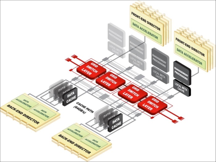
Components of FAST VP:

Comp

Components description:

EMC Symmetrix has two components one is Microcode which resided in Symmetrix Operating system and other is FAST controller residing in Service process.

  1. Performance Data Collection:

Constant performance and CPU utilization of Thin Luns are determined in Sub Lun Levels.

  1. Performance Data Analysis:

Performance data collected are analyzed in the FAST controller.

  1. Intelligent Tiering Algorithm:

Data collected through Micro code and Analysis report generated by FAST controller are used by Intelligent Tiering Algorithm to issue a Sub Lun movement to VLUN VP data Movement Engine.

  1. Allocation Compliance algorithm:

Enforces upper limit of Storage Tier can be used for Sub Lun Data Movement for each Storage groups.

  1. VLUN VP Data Movement Engine:

Based on the Intelligent Tiering algorithm the Extent of data are moved between Tiers.

FAST VP has two modes of operation:

  1. Automatic: Data Movement and Data Analysis are continuously performed.
  2. Off Mode: Only performance statistics will be collected, No data movements will take place.

Elements of FAST VP:

tier

Storage Tier:

Collection of drive technology like EFD, FC, SATA.

Storage Group:

Collection of host accessible devices.

FAST Policy:

Percentage of storage capacity between the storage tiers can be used by storage group.

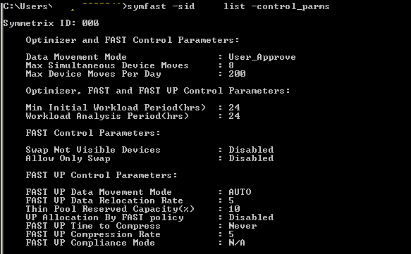
Control Parameters for FAST VP:

  1. Movement Mode: Automatic or Off
  2. Relocation rate: Amount of data that can be moved at a Time. They are measured from 1 to 10, Default value is 5; 1 is the highest value and 10 is the lowest value.
  3. Reserved capacity Limit: Percentage of Virtual pool reserved for Non FAST activity. If we reach this level then FAST movement will not be performed.
  4. Workload analysis time: Amount of work load analysis samples to be collected.
  5. Initial period: Minimum amount of work load analysis needs to be completed before analyzing the sample.

Sample FAST VP control Parameters:

control

Time Windows for FAST VP:

  1. Performance Time Window:

Collecting performance data 24×7. This time window can be changed but not recommended by EMC.

  1. Move Time window:

Time window during which sub Luns can be moved.

FAST implementation steps:

  1. Enable FAST VP.
  2. Set Control Parameters.
  3. Create Storage Tier.
  4. Create FAST Policy.
  5. Associate storage group to FAST Policy.
  6. Enable Time Windows setting.

Pre Checks:

Check for FAST VP licenses:

License can be checked using below command:

Symlmf list –type emclm –sid XXX

Always check with EMC before implementing FAST VP and get the suggestion for control parameters setting and time windows setting.

  1. Enable FAST VP:

Command to enable FAST VP.

Symfast –sid XX enable –vp

To List the states of FAST VP:

Symfast –sid XX list –state

  1. Set Control Parameters settings:

To List control parameters:

Symfast –sid xxx list –control_parms

To change control parameters setting:

symfast -sid XXX set -control_parms -mode AUTO_APPROVE -max_simult_devs 8 -max_devs 240 -min_perf_period 2 -workload_period 24 -vp_data_move_mode AUTO -vp_reloc_rate 5 -pool_resv_cap 20 -vp_allocation_by_fp disable

  1. Create Storage Tier:

Symtier is the command used for creating Storage tier.

RAID protection for Tier creation:

RAID 0 = -tgt_unprotected 
RAID 1 = -tgt_raid1 
RAID 5 = -tgt_raid5 -tgt_prot 3+1, -tgt_raid5 -tgt_prot 7+1
RAID 6 = -tgt_raid6 -tgt_prot 6+2 , -tgt_raid6 -tgt_prot 14+2

We had already created three pools named EFD,FC,SATA.

Creating EFD Tier:

symtier -sid xxx create -name EFD_VP_Tier -tgt_raid5 -tgt_prot 7+1 -technology EFD -vp -pool PoolName –EFD

 Creating FC Tier:

 symtier -sid xxx create -name FC_VP_Tier -tgt_raid5 -tgt_prot 3+1 -technology FC  -vp -pool PoolName –FC

 Creating SATA Tier:

 symtier -sid xxx create -name FC_SATA_Tier -tgt_rai6 -tgt_prot 6+2 -technology SATA  -vp -pool PoolName –SATA

 To List Tiers:

Symfast –sid XXX list

1

4. Create FAST Policy:

Create FAST VP policy.

symfast -sid xxx -fp create -name EFD_VP

Add Storage Tiers to FAST Policy.

symfast -sid xxx -fp add -tier_name EFD_VP_Tier  -max_sg_percent 100 -fp_name EFD_VP

symfast -sid xxx -fp add -tier_name FC_VP_Tier -max_sg_percent 20 -fp_name EFD_VP

symfast -sid xxx -fp add -tier_name SATA_VP_Tier -max_sg_percent 10 -fp_name EFD_VP

Maximum 300% for Storage tier can be allocated to a FAST Policy.

To list FAST VP policy:

Symfast list –sid 606 –fp -vp


2

5. Associate storage group to FAST Policy:

Storage groups will be created while Auto provisioning for a host.

Associate a Storage group to a FAST policy.

symfast -sid xxx associate -sg Storage_group -fp_name EFD_VP -priority 2 

Storage group associated with fast policy will be assigned a priority between 1 to3. 1 is highest, 3 is lowest and 2 is default priority. 

To List association: 

symfast -sid xxx list –association 

6. Enable Time Windows setting: 

To List Time window:

Symtw list –sid XXX

To Change the Move Time Window setting: 

symtw -sid XXX add -type MOVE_VP -days mon,tue,wed,thu,fri,sat,sun -start_time 18:00 -end_time 24:00 –inclusive

 To Change performance Time Window:

symtw -sid xxx -inclusive -type perf add -days Mon,Tue,Wed,Thu,Fri,Sat,Sun -start_time 00:00 -end_time 24:00

Mostly Performance time windows are not changed. Default time windows are preferred for performance time window setting.

Inter Fabric Links

The link between an E_Port and EX_Port, or VE_Port and VEX_Port, is called an inter-fabric link (IFL). IFLs can be achieved using a FC router.

Why IFLs is needed?

IFL needs to be implemented when there is a need to have a communication with different Fabric without disturbing the current setup. IFL can be achieved with use of FC router.

Meta SAN:

Meta-SAN is a collection of SAN devices, switches, edge fabrics, Logical Storage Area Networks (LSANs), and Routers that comprise a physically connected but logically partitioned storage network.

Meta SAN Example:

LSAN

Terms to be known:

Backbone Fabric: A capability that enables scalable Meta SANs by allowing the networking of multiple routers that connects to the backbone fabric via E_Port interfaces. A backbone fabric is an intermediate network that connects two or more edge fabrics. A backbone fabric also enables hosts and targets in one edge fabric to communicate with devices in other edge or backbone fabrics.

Backbone-to-Edge Routing: Fibre Channel routers can connect to a common fabric–known as a backbone fabric E_Ports. A backbone fabric can be used as a transport fabric that interconnects edge fabrics. Fibre Channel routers also enable hosts and targets in edge fabrics to communicate with devices in the backbone fabric–this is known as backbone-to-edge routing.

E_Port: A standard Fibre Channel mechanism that enables switches to network with each other.

Edge Fabric: A Fibre Channel fabric connected to a router via one or more EX_Ports. This is where hosts and storage are typically attached in a Meta-SAN.

Edge-to-Edge Routing: Occurs when devices in one edge fabric communicate with devices in another edge fabric through one or more Fiber Channel routers.

EX_Port: The type of E_Port used to connect a router to an edge fabric. An EX_Port follows standard E_Port protocols.

Exported Device: A device that has been mapped between fabrics. A host or storage port in one edge fabric can be exported to any other fabric through LSAN zoning.

Fabric ID (FID): Unique identifier of a fabric in a Meta-SAN. Every EX_Port and VEX_Port uses the FID property to identify the fabric at the opposite end of the IFL. You should configure all of the EX_Ports and VEX_Ports attached to the same edge fabric with the same FID. The FID for every edge fabric must be unique from each backbone fabric’s perspective.

Fibre Channel Network Address Translation (FC-NAT): A capability that allows devices in different fabrics to communicate when those fabrics have addressing conflicts. This is similar to the “hide-behind” NAT used in firewalls.

Fibre Channel Router Protocol (FCRP): A Brocade-authored standards-track protocol that enables LSAN switches to perform routing between different Edge fabrics, optionally across a backbone fabric.

FC-FC Routing Service: A service that extends hierarchical networking capabilities to Fibre Channel fabrics. It enables devices located on separate fabrics to communicate without merging the fabrics. It also enables the creation of LSANs.

Inter-Fabric Link (IFL): A connection between a router and an edge fabric. Architecturally, these can be of type EX_Port-to-E_Port or EX_Port-to-EX_Port.

Logical Storage Area Network (LSAN): A logical network that spans multiple fabrics. The path between devices in an LSAN can be local to an edge fabric or cross one or more Routers and up to one intermediate backbone fabric. LSANs are administered through LSAN zones in each edge fabric.

LSAN Zone: The mechanism by which LSANs are administered. A Router attached to two fabrics will “listen” for the creation of matching LSAN zones on both fabrics.

Meta-SAN: The collection of all devices, switches, edge and backbone fabrics, LSANs, and Routers that make up a physically connected but logically partitioned storage network

Phantom Domains: A phantom domain is a domain created by the Fibre Channel router. The FC router creates two types of phantom domains: front phantom domains and translate phantom domains.

Front phantom domain or front domain: a domain that is projected from the FC router to the edge fabric. There is one front phantom domain from each FC router to an edge fabric, regardless of the number of EX_Ports connected from that router to the edge fabric. Another FC router connected to the same edge fabric projects a different front phantom domain.

Translate phantom domain: Also known as  xlate domain, is a router virtual domain that represents an entire fabric. The EX_Ports present xlate domains in edge fabrics as being topologically behind the front domains; if the xlate domain is in a backbone fabric, then it is topologically present behind the FC router because there is no front domain in a backbone fabric.

Proxy Devices: A proxy device is a virtual device presented into a fabric by a Fibre Channel router, and represents a real device on another fabric. When a proxy device is created in a fabric, the real Fibre Channel device is considered to be imported into this fabric. The presence of a proxy device is required for inter-fabric device communication. The proxy device appears to the fabric as a real Fibre Channel device, has a name server entry, and is assigned a valid port ID. The port ID is only relevant on the fabric in which the proxy device has been created.

Proxy ID:– The port ID of the proxy device.

VE_Port: Virtual E_Port; an FCIP tunnel without routing is a VE_Port.

VEx_Port: The type of VE_Port used to connect a router to an edge fabric. A VEx_Port follows standard E_Port protocols and supports FC-NAT but does not allow fabric merging across VEX_Ports.

How Inter Fabric Link Works?

Let’s take a below example for Inter fabric Link and how it can be achieved.

FC Routing

In this example there are two separate fabrics in Fabric A storage node is connected and in Fabric B Host server is being connected. Now due to urgent requirement for additional storage there is a need for allocating 1 TB of storage to an Host in Fabric B, There is a problem now because Storage Node is present in Fabric A and Host server cannot contact storage as they are in different fabric. To solve this problem there is a introduction of FC routing concept and this is achieved using a FC router being connected to a Edge switch from both fabric. Now the Devices connected in a Fabric can communicate with Devices in Fabric B using Inter Fabric links and this concept is known as FC routing. Whole Fabric A and Fabric B connected through a FC router is called as LSAN.

How communications between 2 Fabrics occur?

Below are the steps involved in IFL communication.

Step 1: Disable the ports in Edge switch to be participated in IFLs

Step 2: Cable Edge switches of both fabric to FC router.

Step 3: Convert FC Router port as EX port, can be achieved using FC router Web Tools or Command Line.

Step 4: While configuring EX port set Fabric Id of the ports, Fabric Id should not be 1.

Step 5: Enable the ports. Now this will take some time communication between E and Ex ports.

Step 6: Now the If we want Host from Fabric B to access Fabric A we need to do LSAN Zoning.

Step 7: Create a Zone in Fabric B as LSAN_Zone Name and add Host WWPN and Storage WWPN in target side to get communicated. Enable the Zone configuration.

Step 8: Similarly Create a Zone in Fabric A as LSAN_Zone Name and Host WWPN and Storage WWPN in target side to get communicated. Enable the Zone configuration.

Step 9: When LSAN zoning has been done it takes some time to have a communication because FC Routing gets initialized when LSAN zoning gets completed.

Step 10: When communication gets established the Fabric A sees the Host as a Proxy Device present in Fabric A with Proxy Id, Similarly Fabric B sees the Storage Node as a Proxy Device with Proxy Id. Now the storage can be allocated to Fabric B host server.